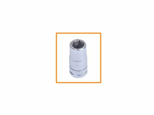
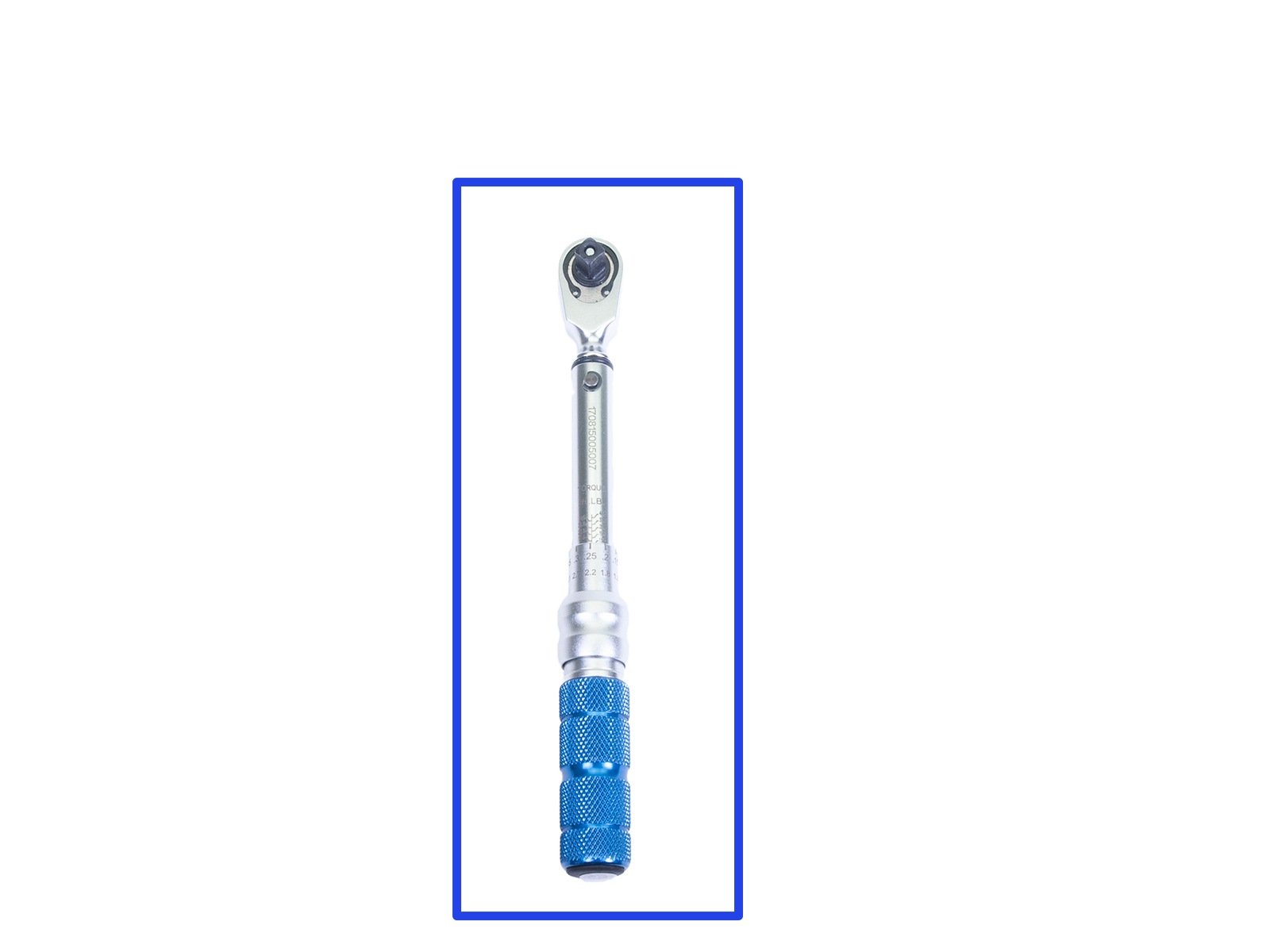
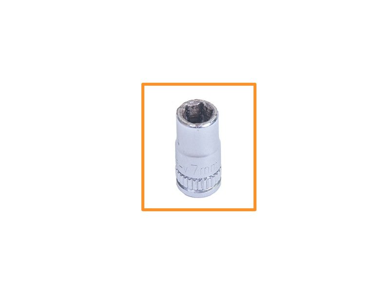
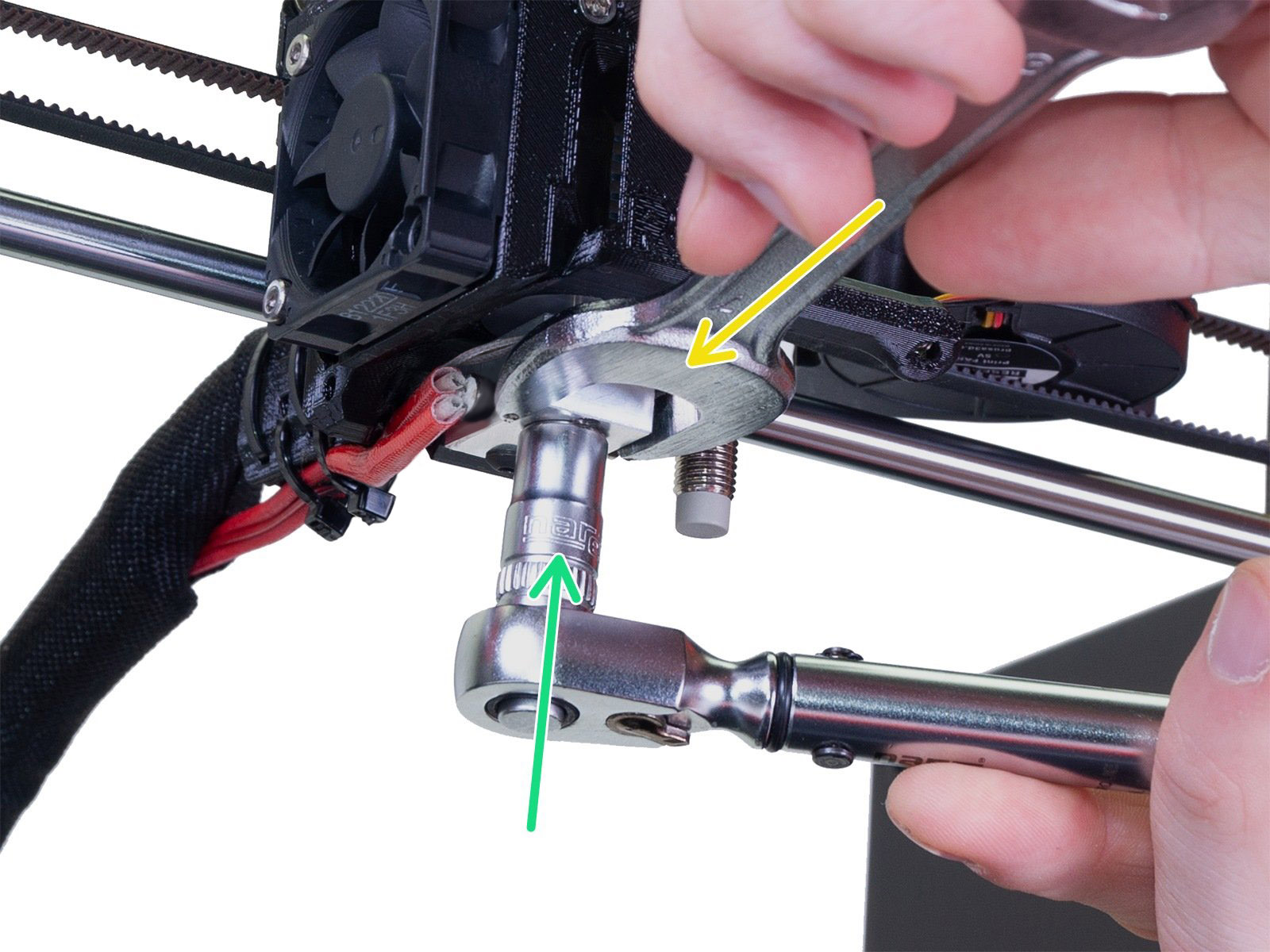
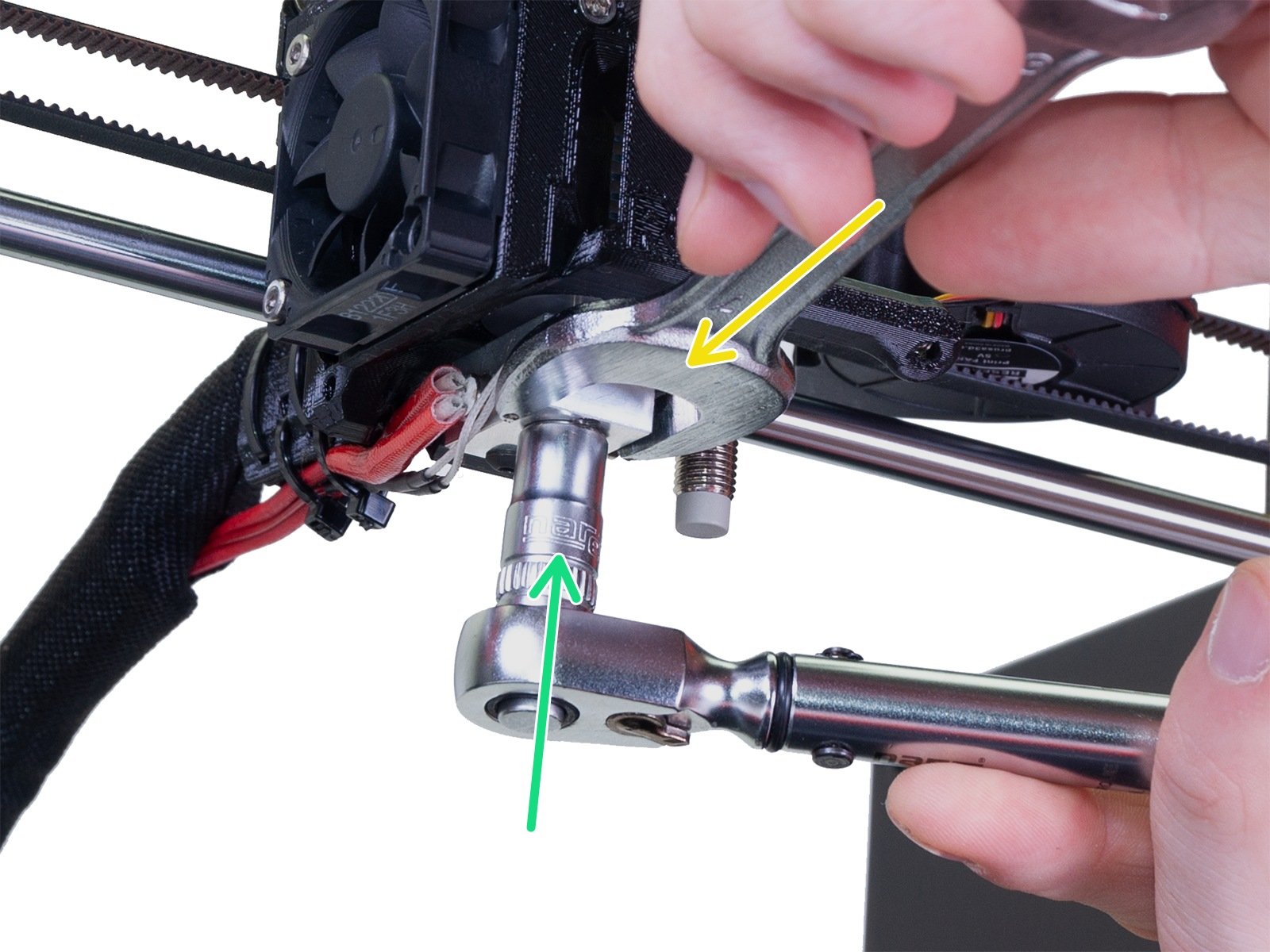
⬢Some torque wrenches are not intended for loosening. Read the instructions for your torque wrench. Alternatively, you can use a ratchet or a side wrench size 7 mm / 0.28".
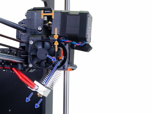
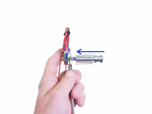
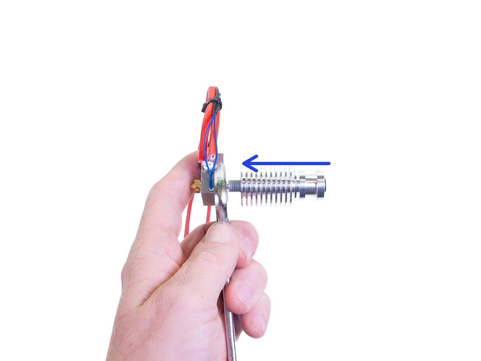
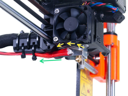
⬢With one hand, hold the heaterblock using the wrench size 16 (0.63"). Place the wrench under the cables to avoid damage.
⬢With the other hand, use a torque wrench, place it on the nozzle and slightly loosen it. Do not remove the nozzle at the moment.
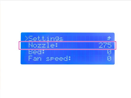
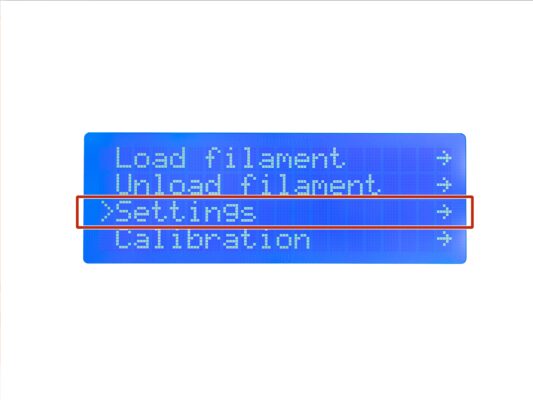
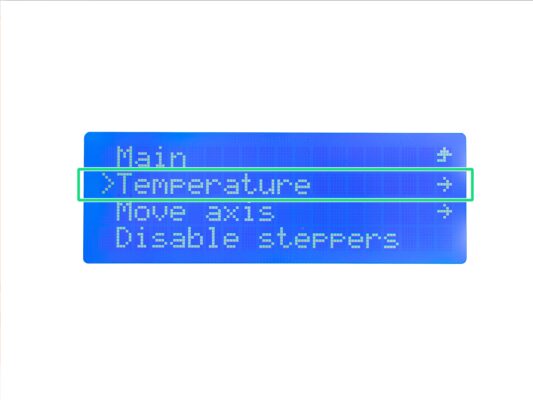
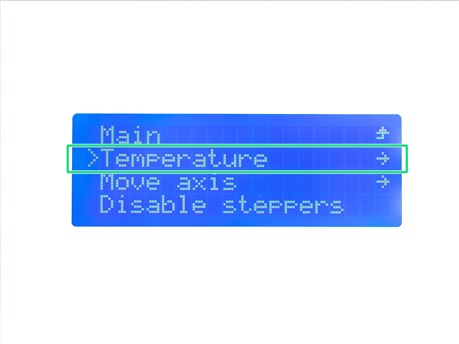
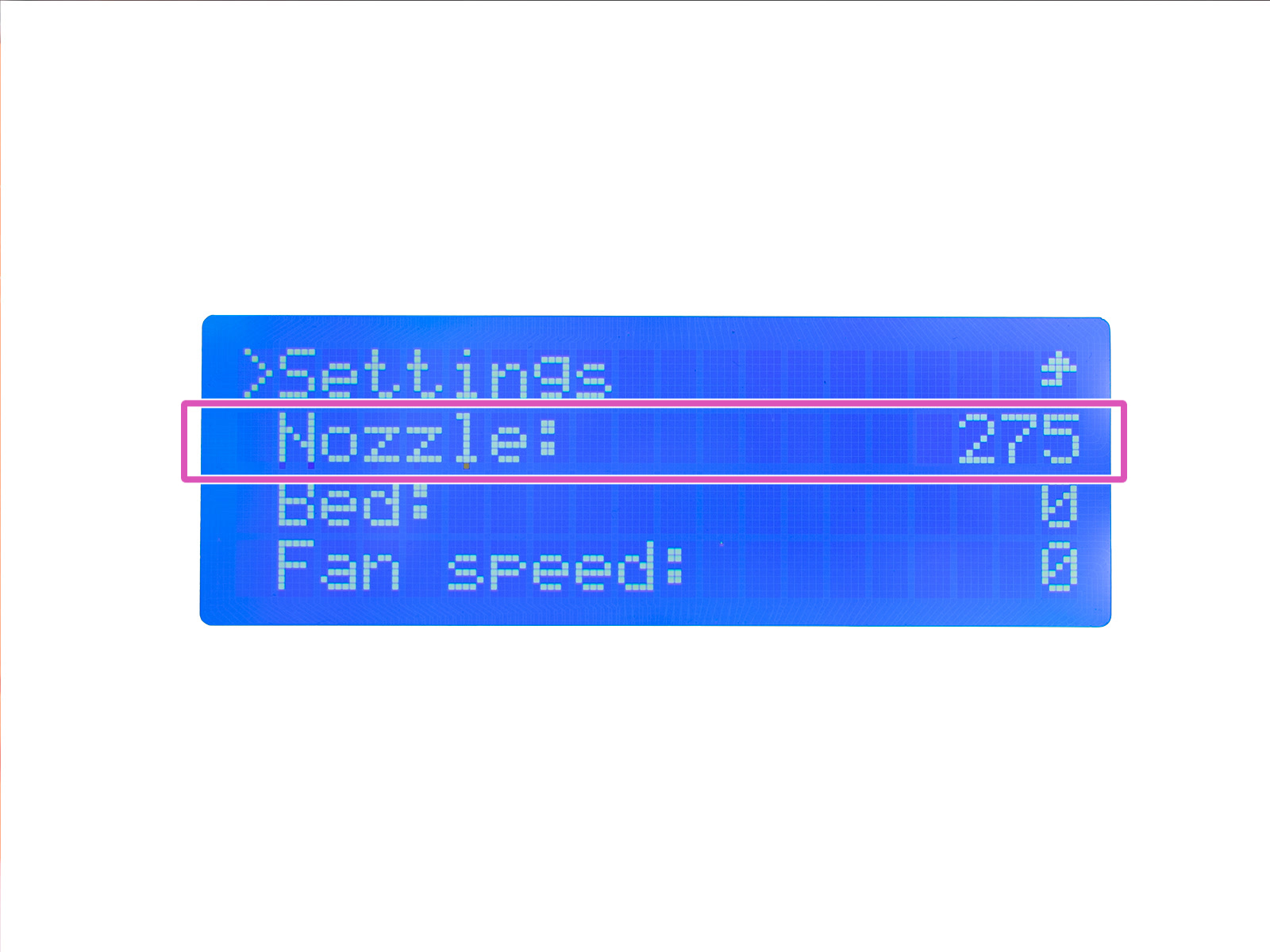
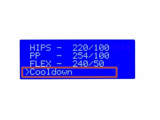
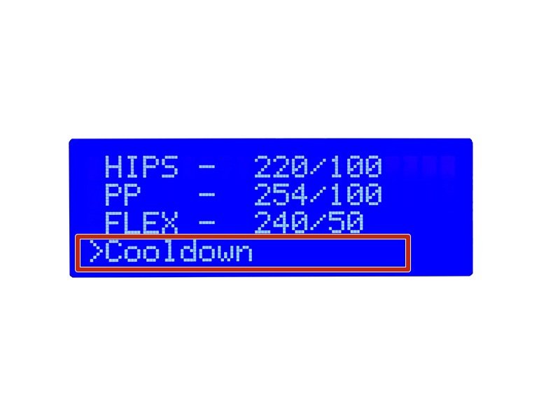
⬢Navigate to the Preheat menu and at the end of the menu select Cooldown.
Wait for 15 - 20 minutes to ensure the hotend is cooled down completely before proceeding to the next step.
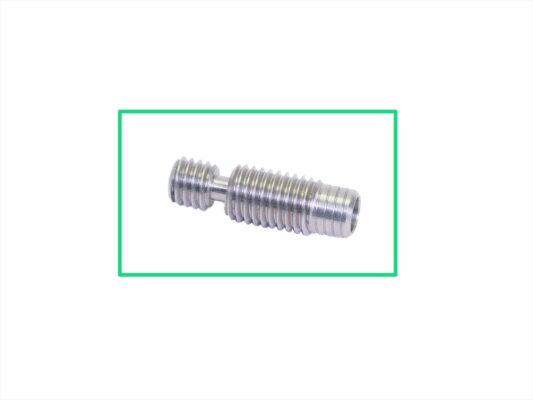
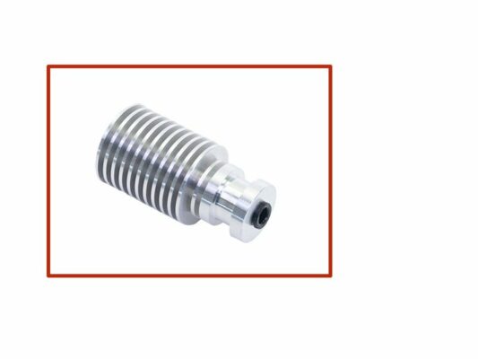
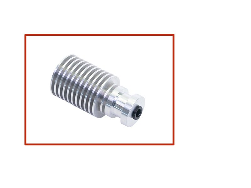
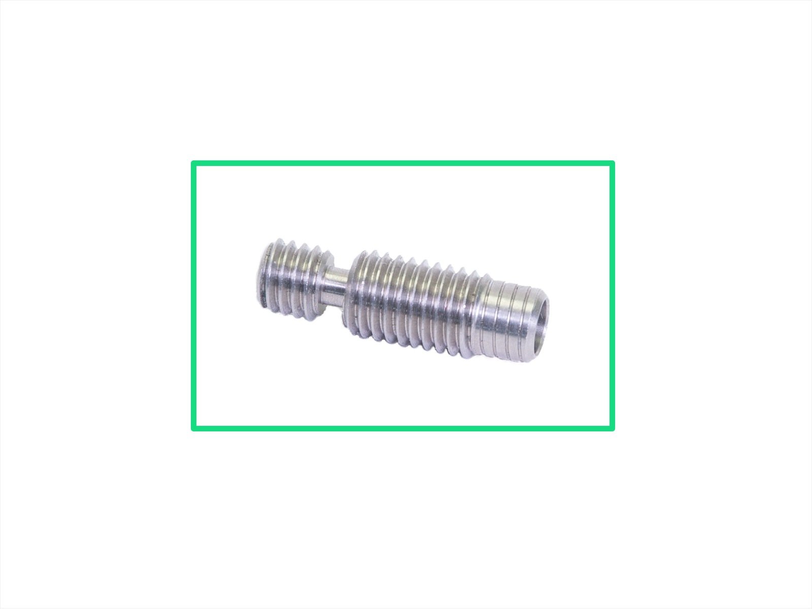
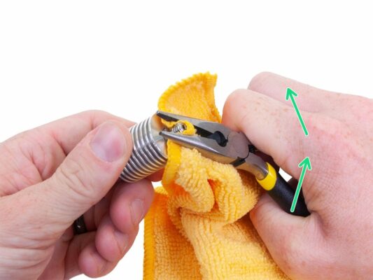
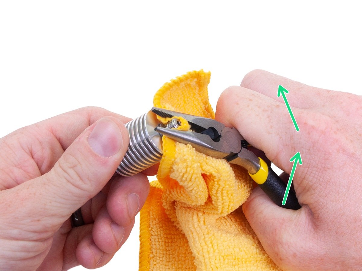
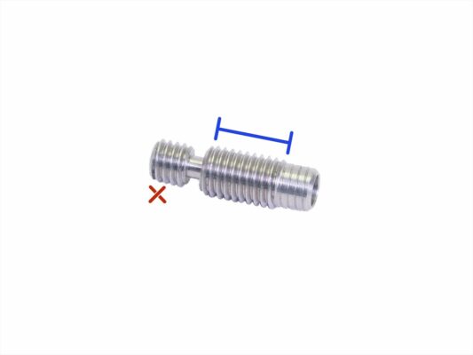
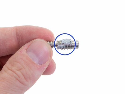
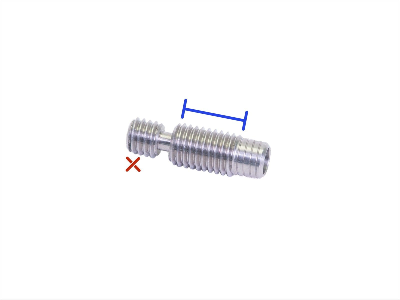
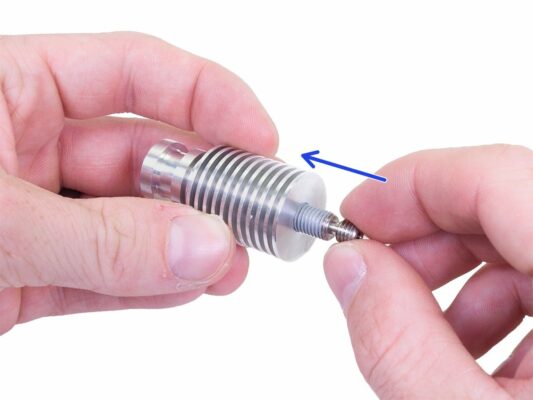
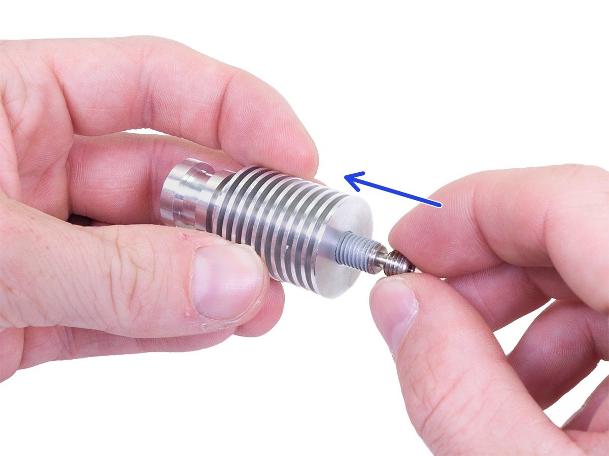
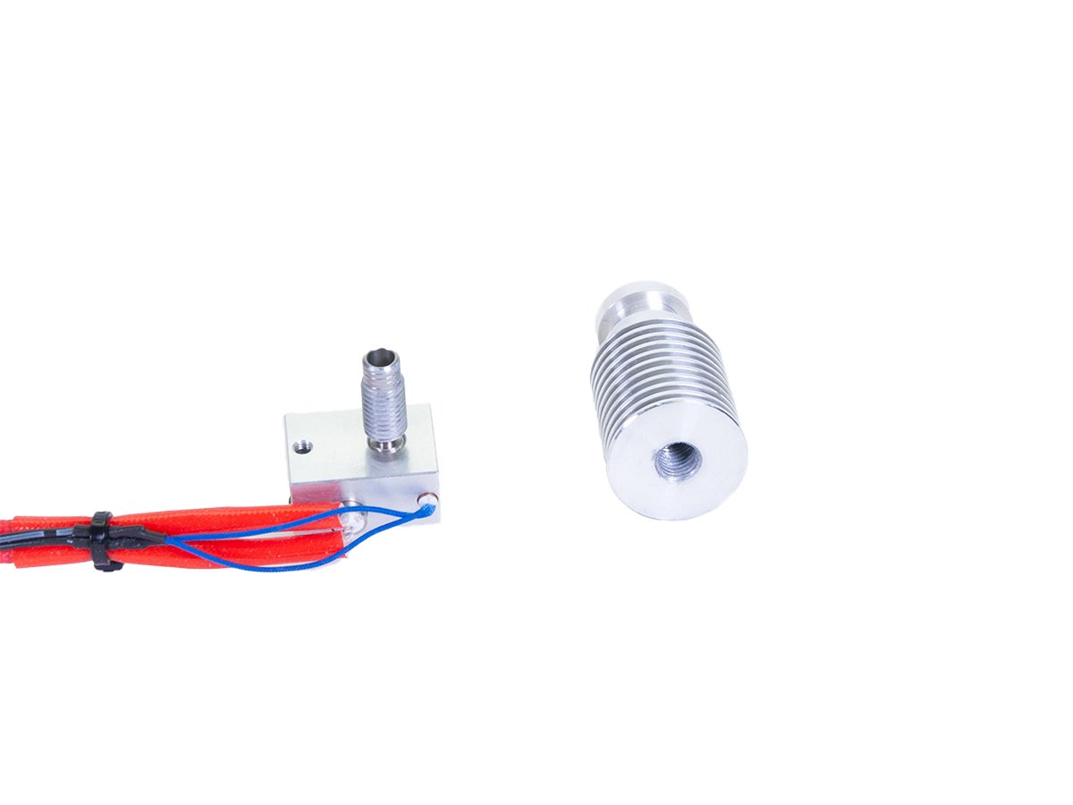
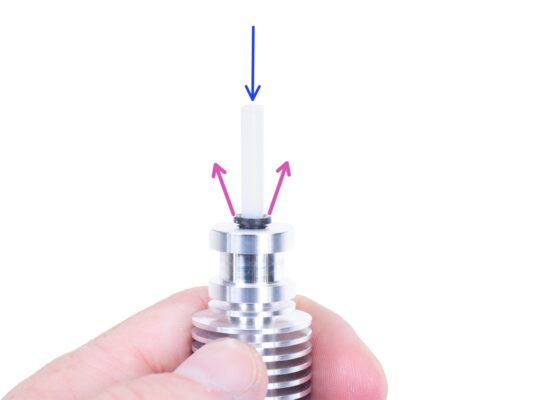
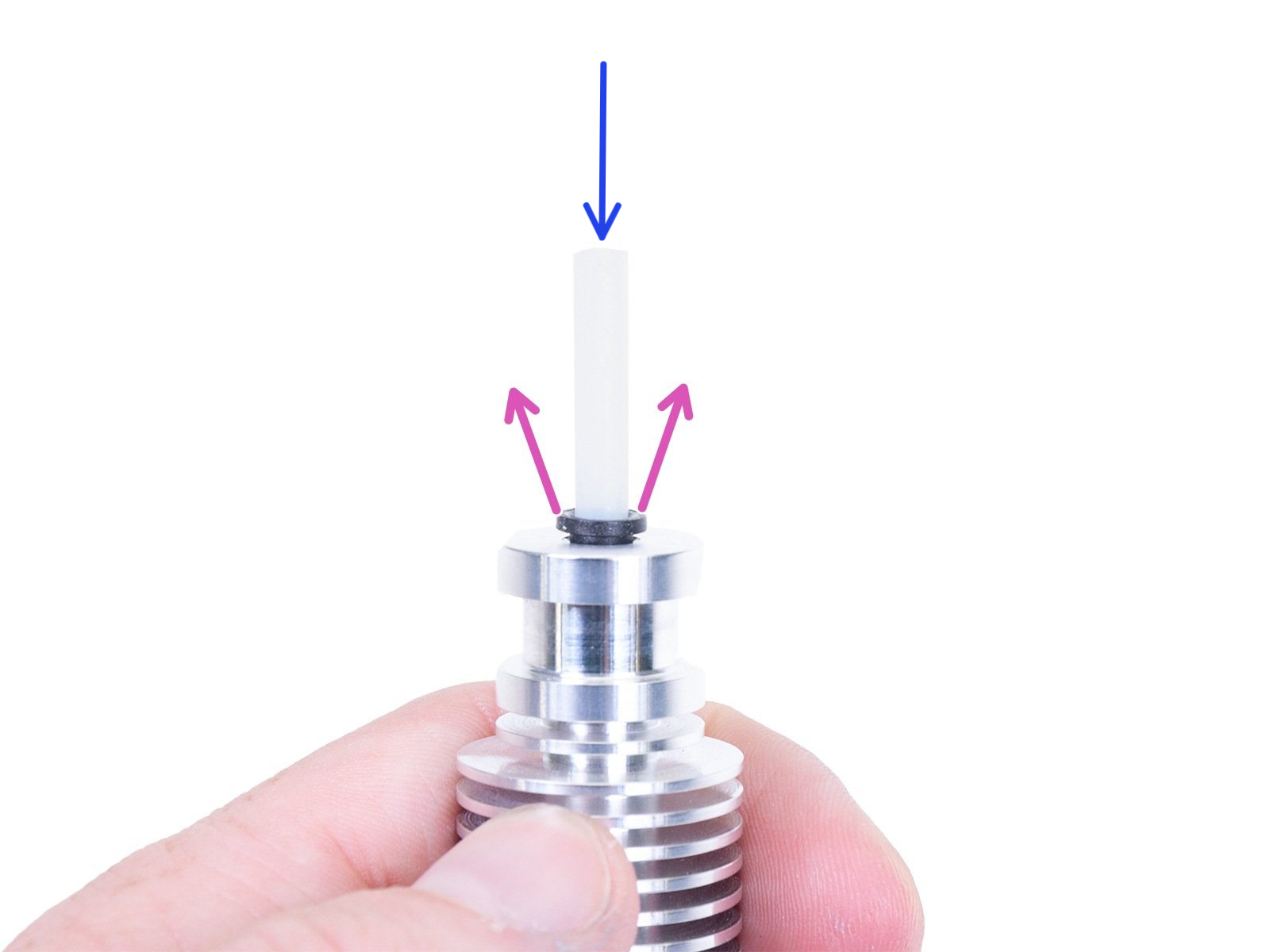
⬢Take the new heatbreak and apply most of the content of the thermal paste package on the long thread. Spread it evenly with a paper towel.
Do not apply the paste on the short thread!:
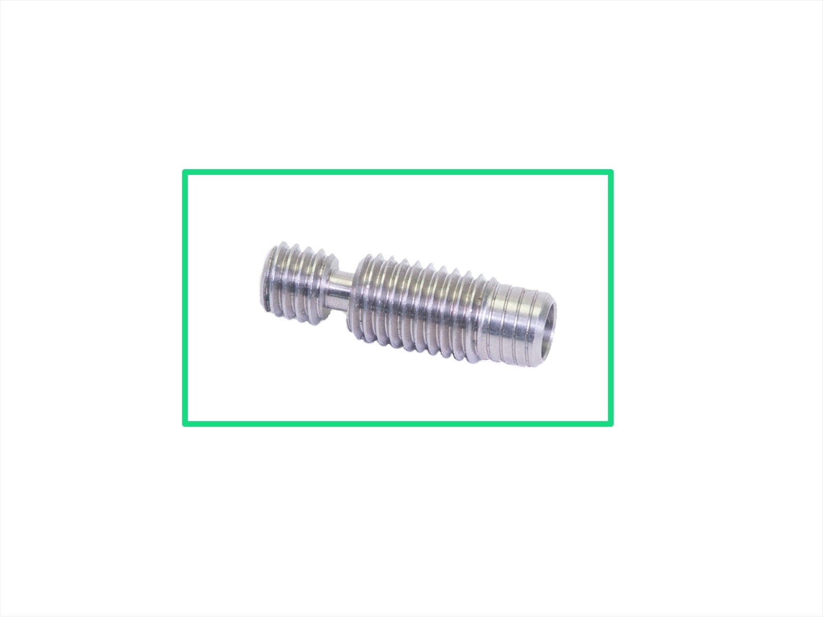
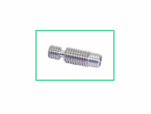
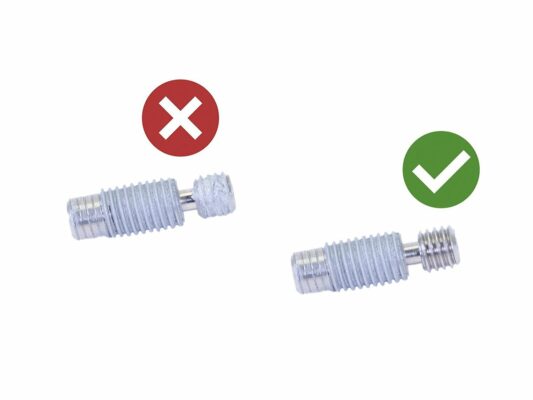
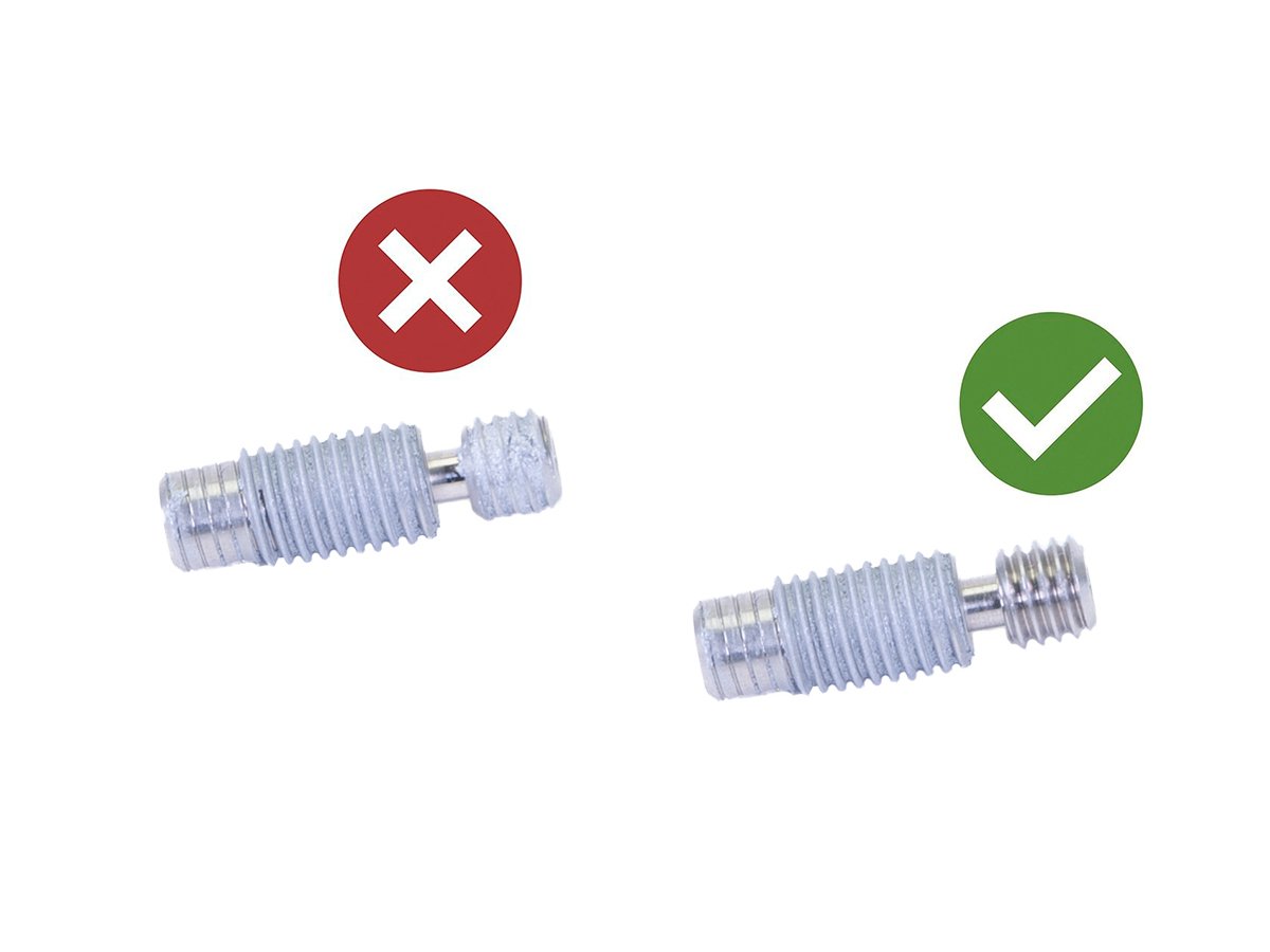
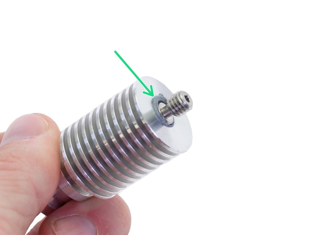
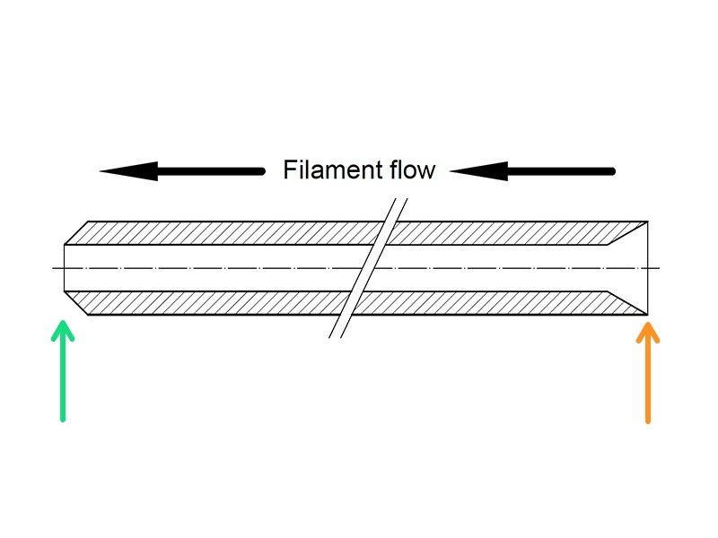
⬢Incorrect application: the thermal paste is covering both threads of the heatbreak.
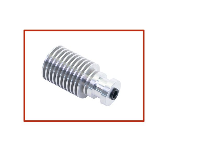
⬢Correct application: the thermal paste is covering on the long thread of the heatbreak.
Applying the paste on the short thread can later lead to a gap between the heatbreak and the nozzle. The nozzle might then become clogged when the filament is loaded.
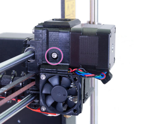
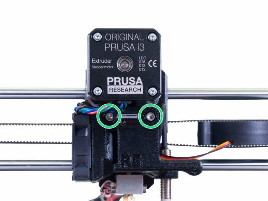
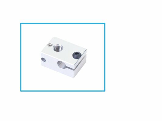
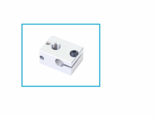
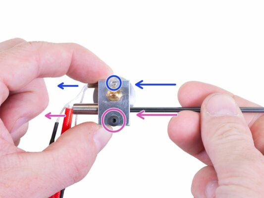
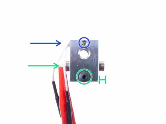
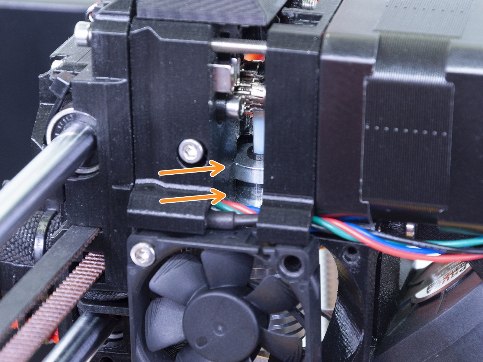
⬢Insert the thermistor to the new heaterblock and secure by tightening the lock screw.
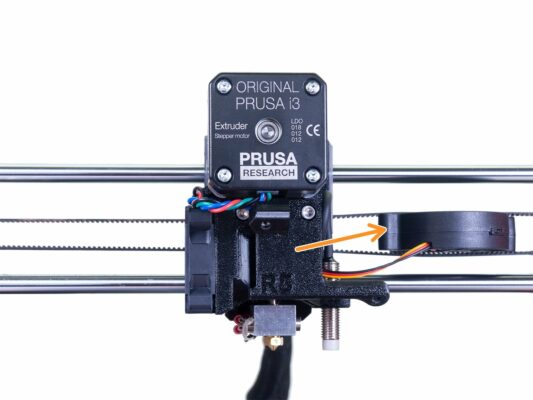
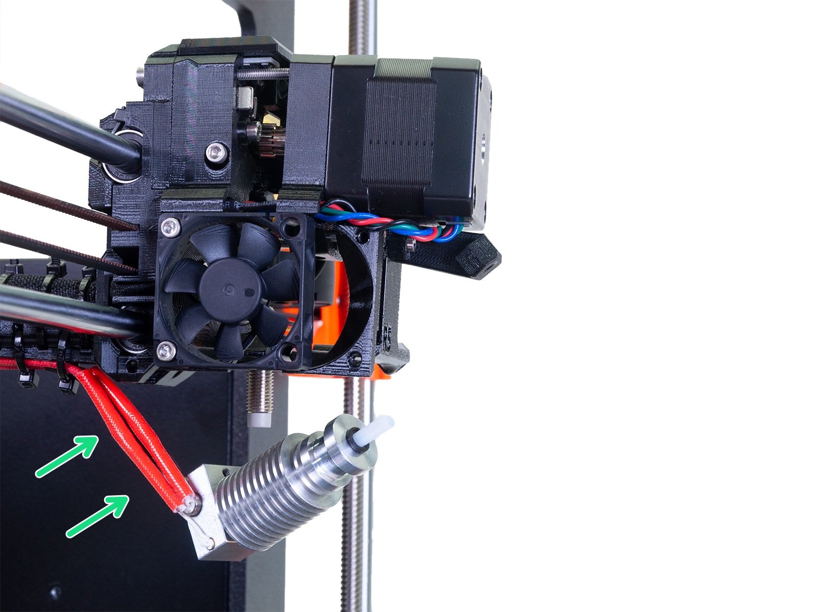
⬢Then insert the heater to the heaterblock and secure it by tightening the black screw. Make sure the heater hangs over on the right side, see the picture.
Ensure both thermistor and the heater are properly inserted and tightened!
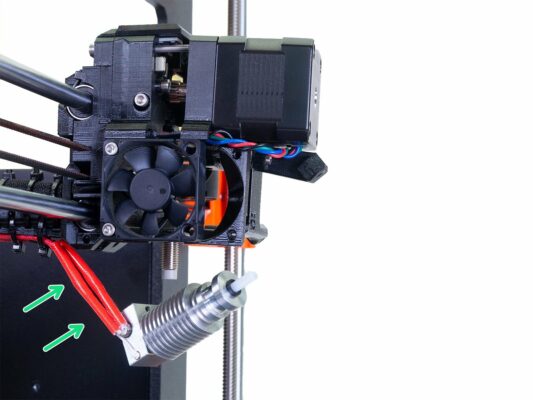
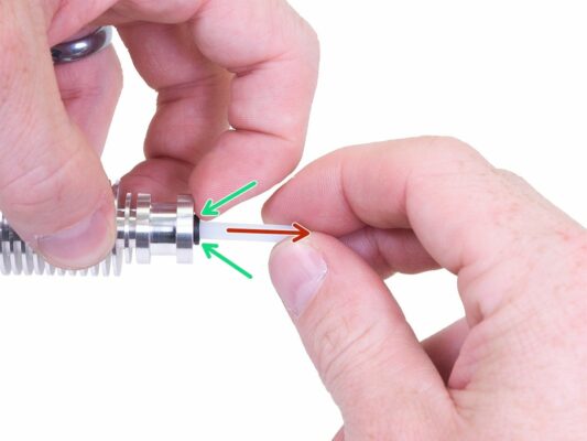
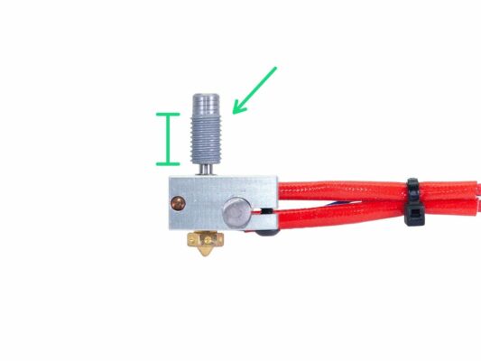
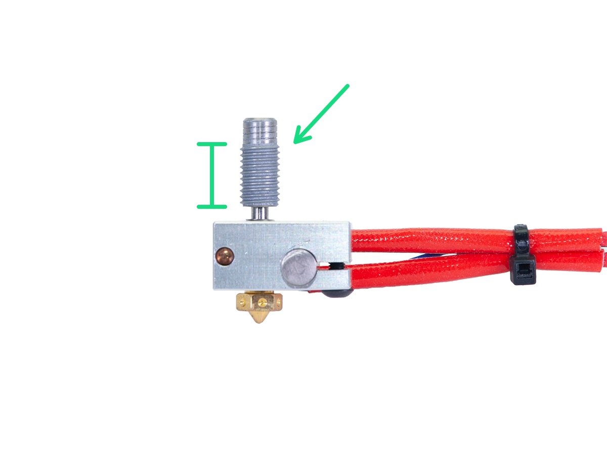
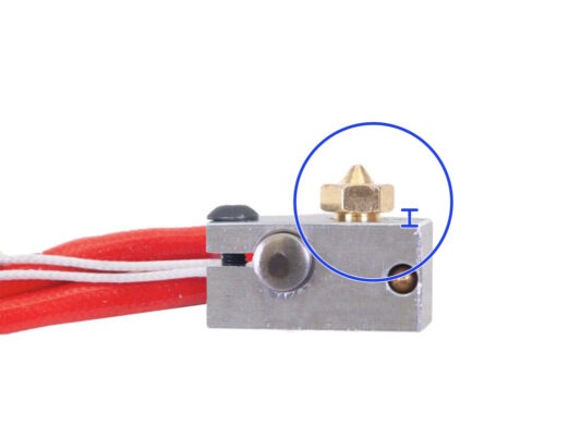
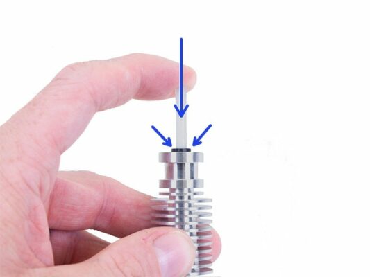
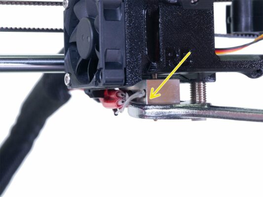
⬢Screw the nozzle slightly in the heaterblock. Create a gap about 0,5 mm (0.02 inch), see the picture.
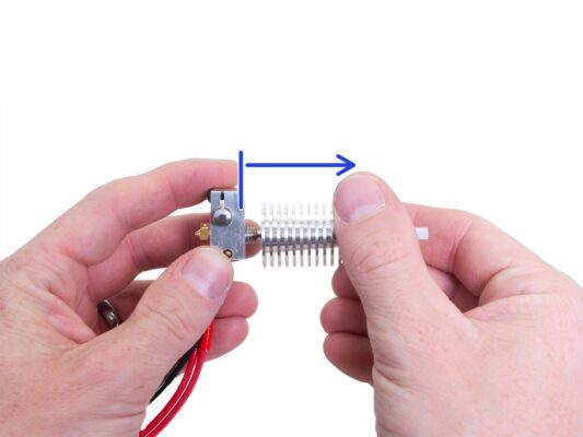
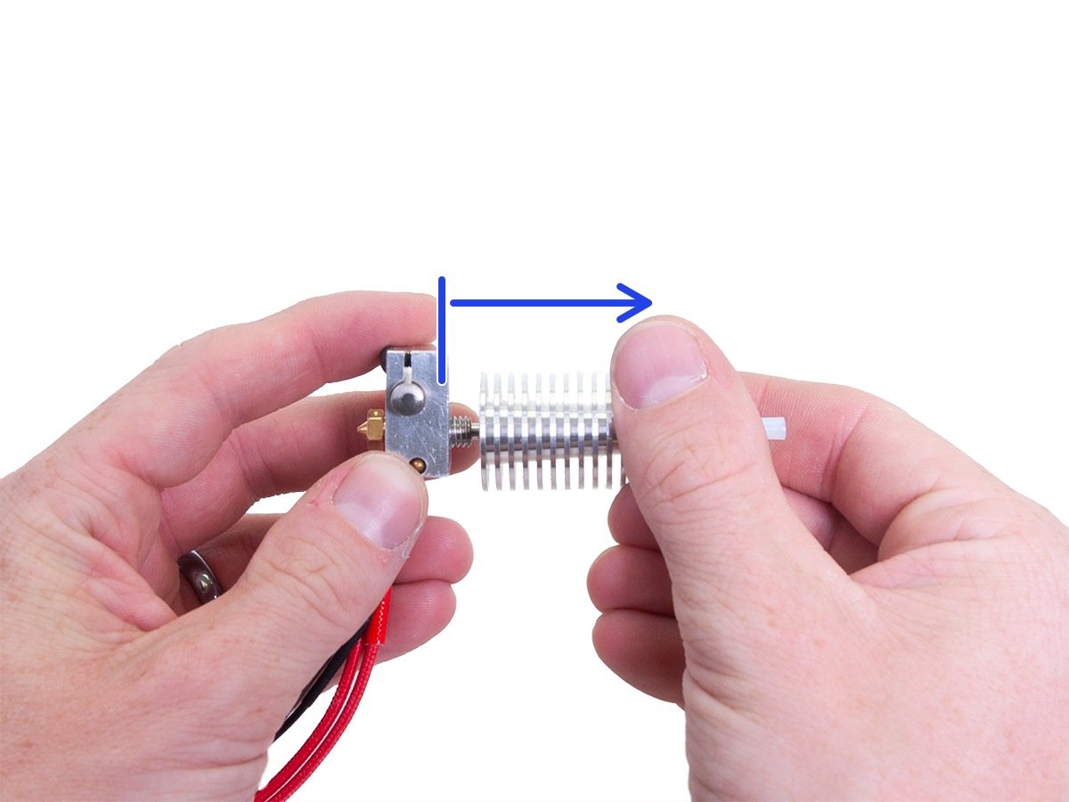
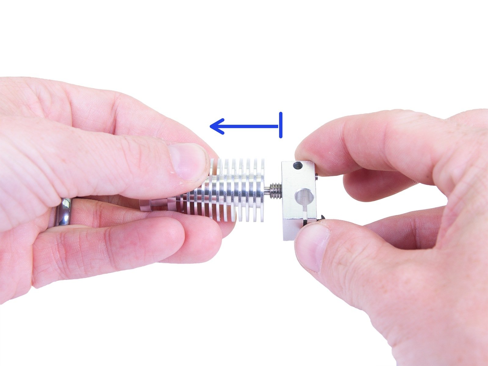
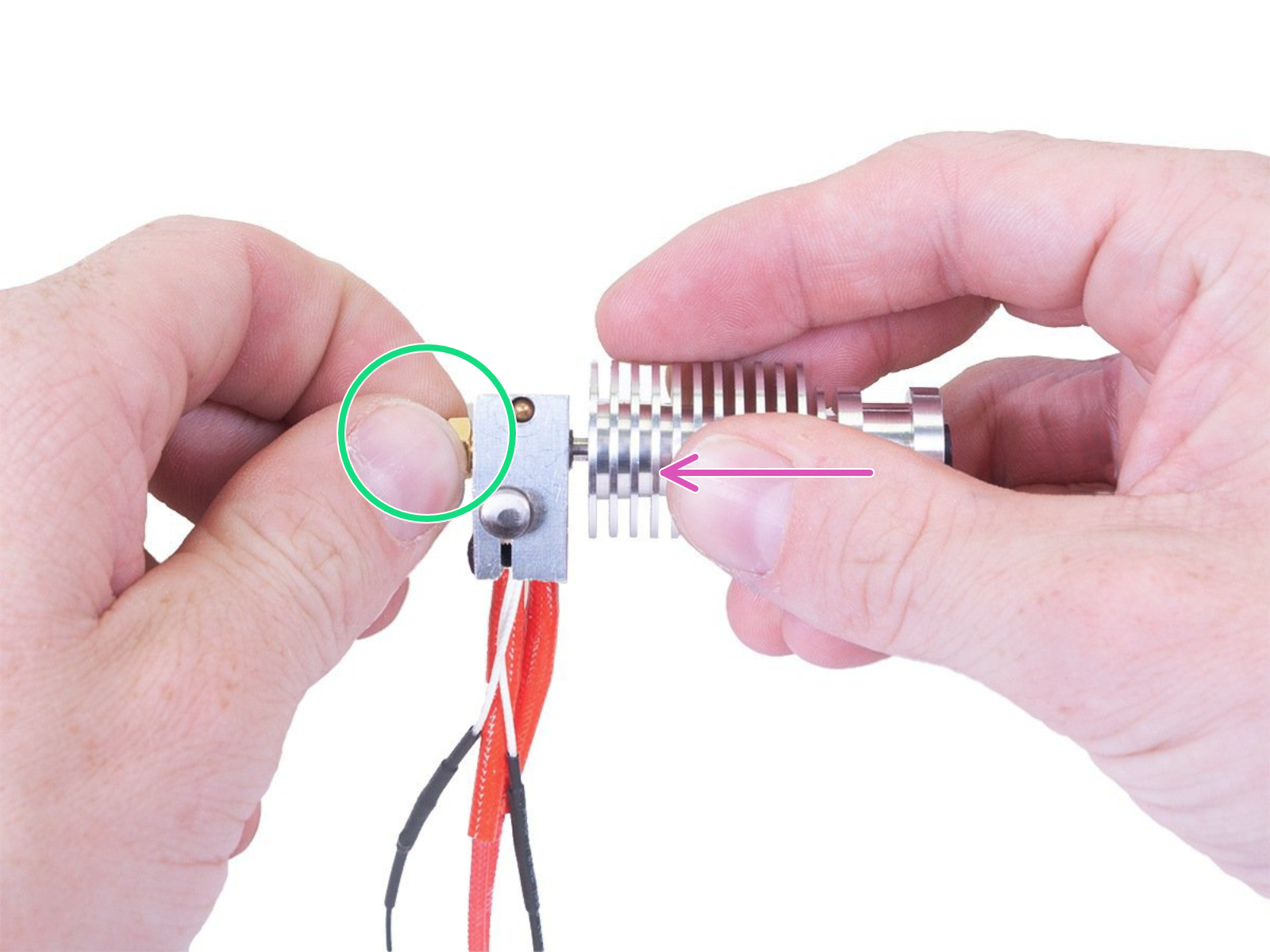
⬢Secure the nozzle against movement with one hand.
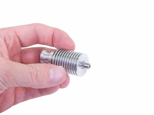
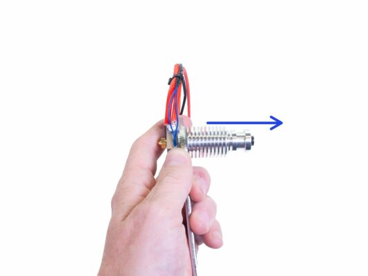
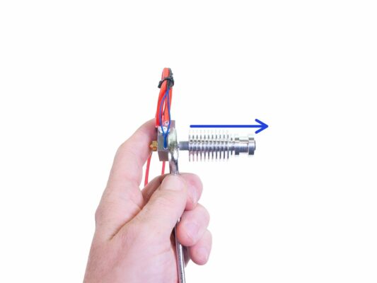
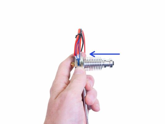
⬢With the other hand, screw the heatbreak with heatsink into the heaterblock from the opposite side until it touches the nozzle inside. Do not tighten anything by torque wrench at the moment.
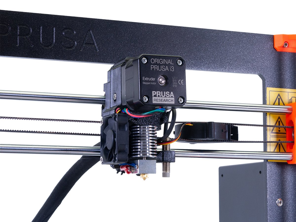
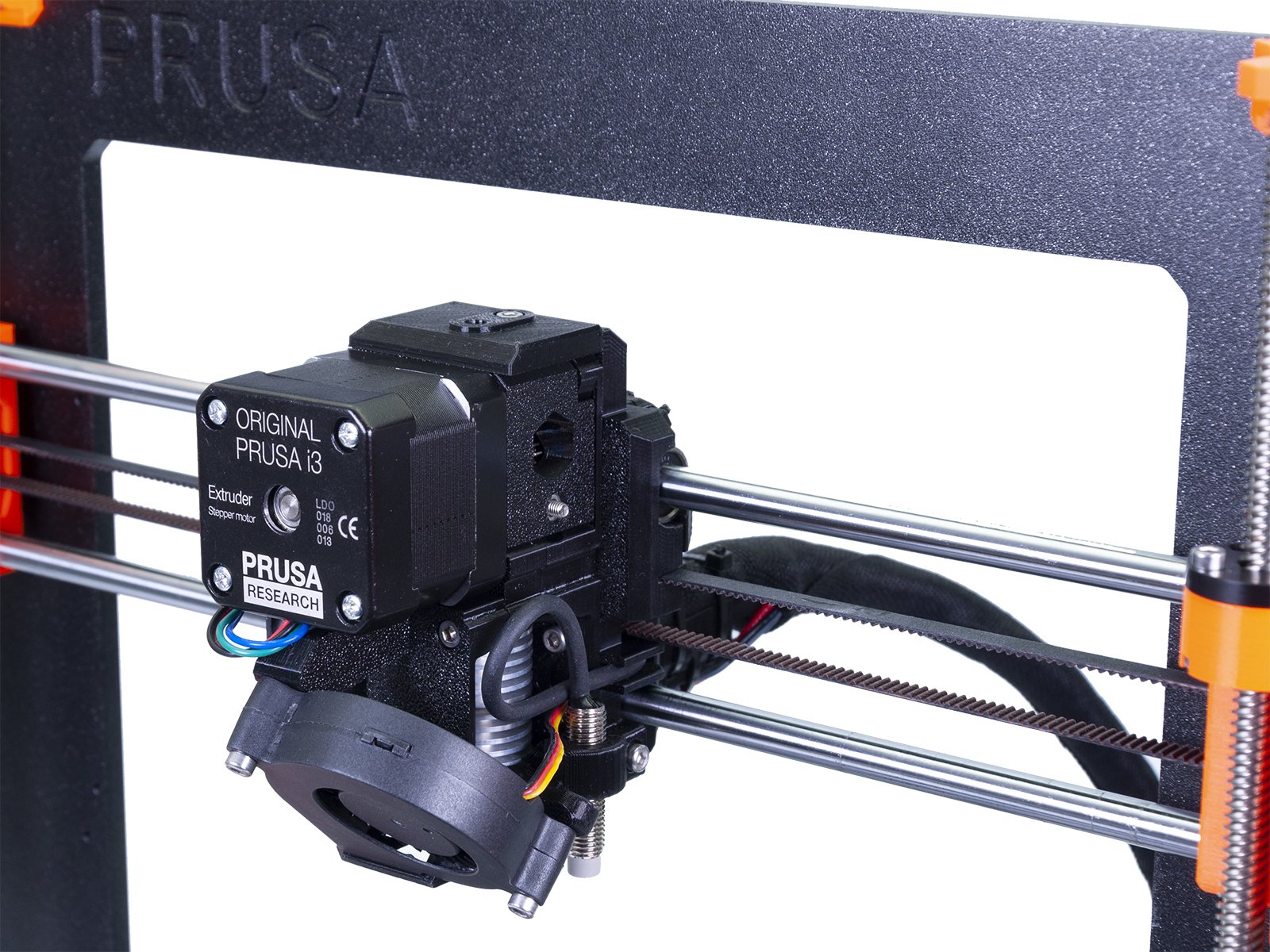
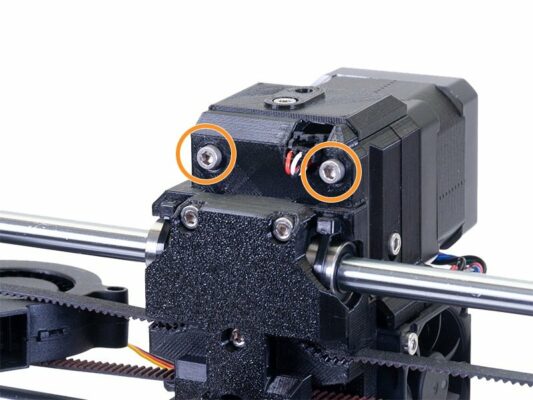
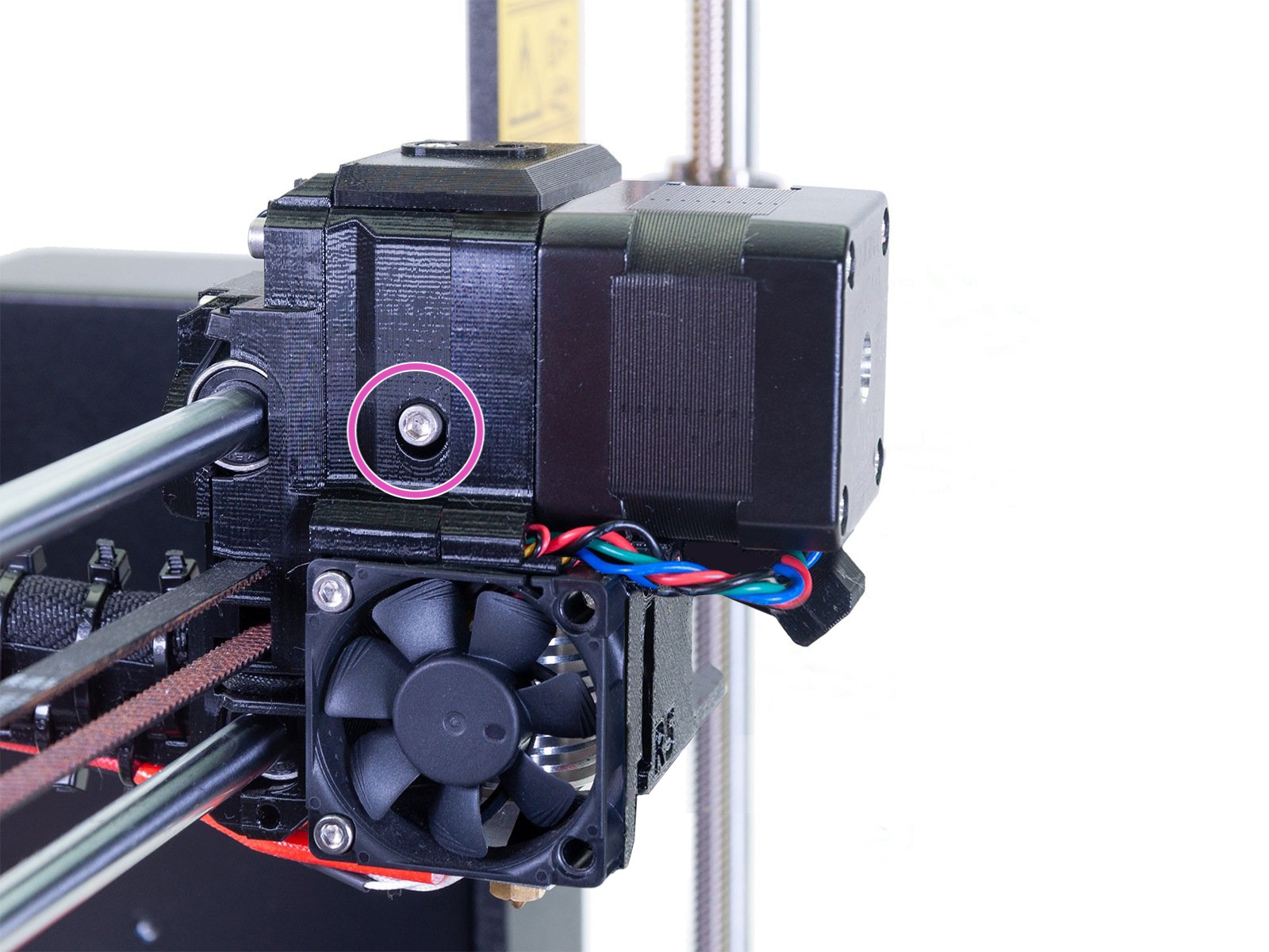
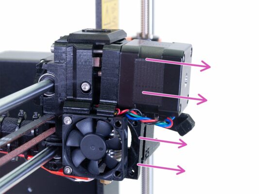
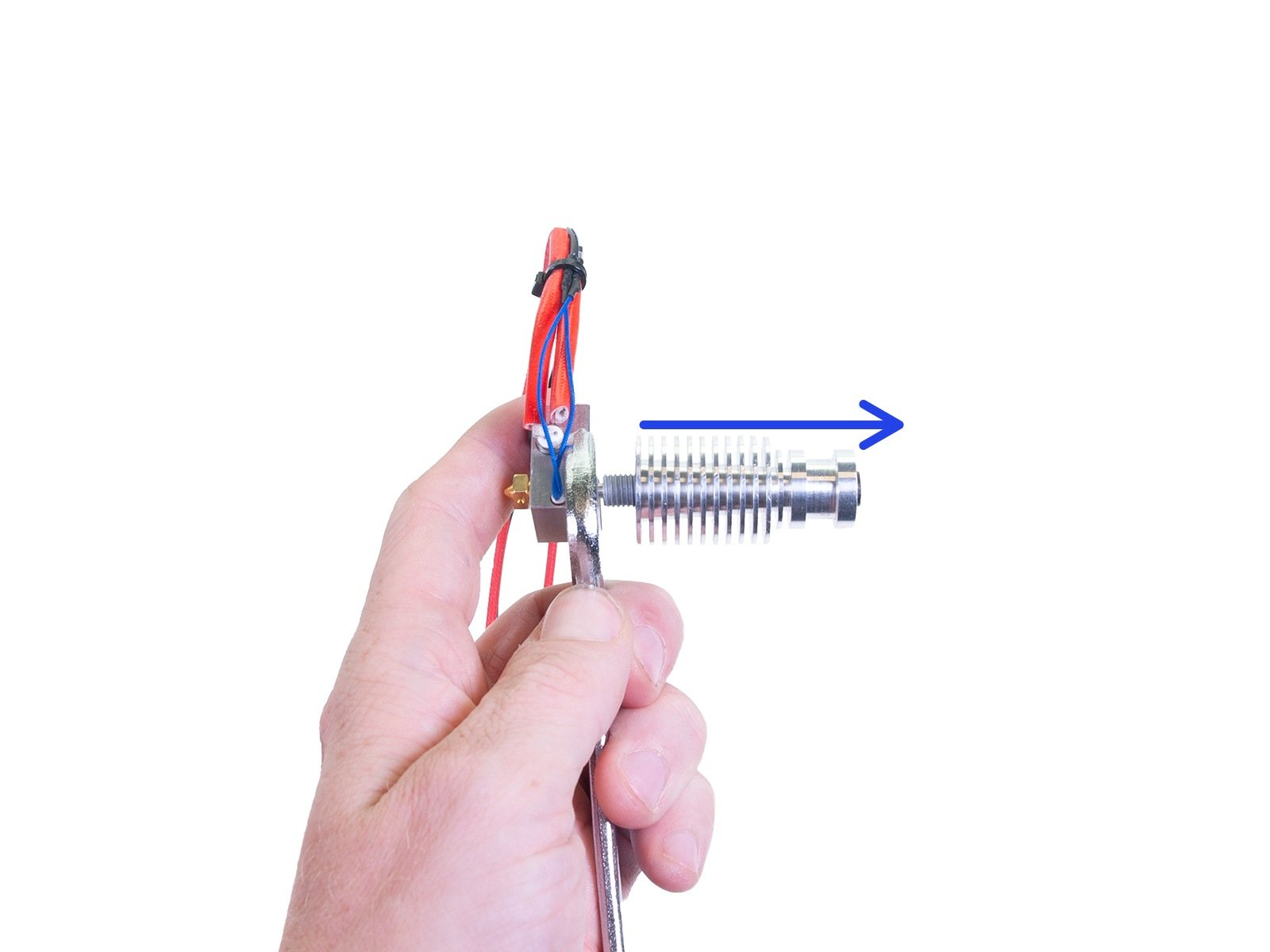
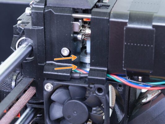
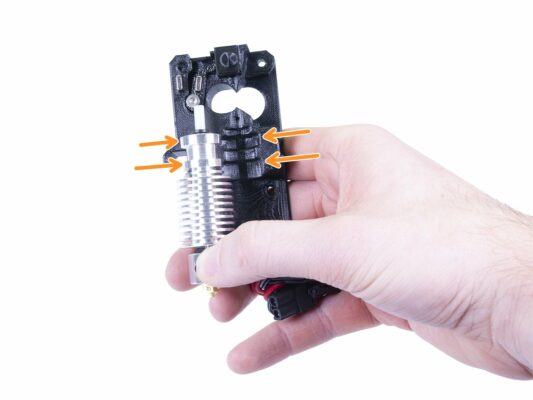
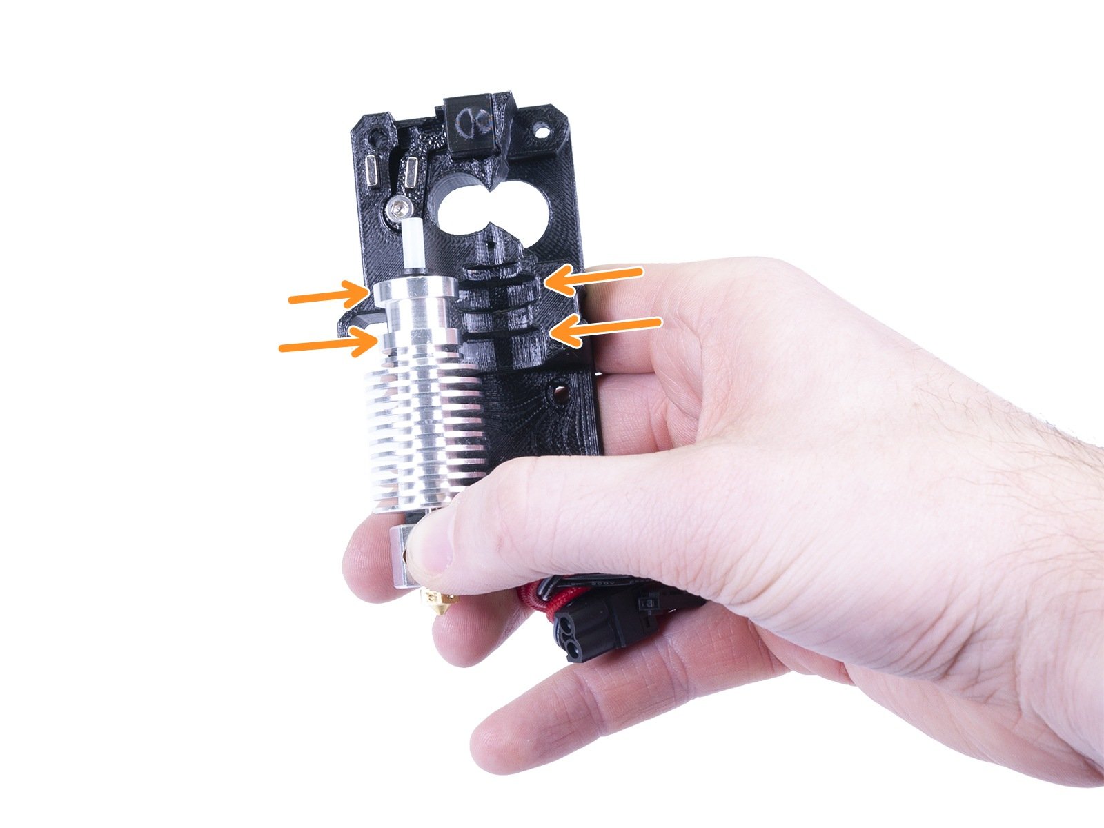
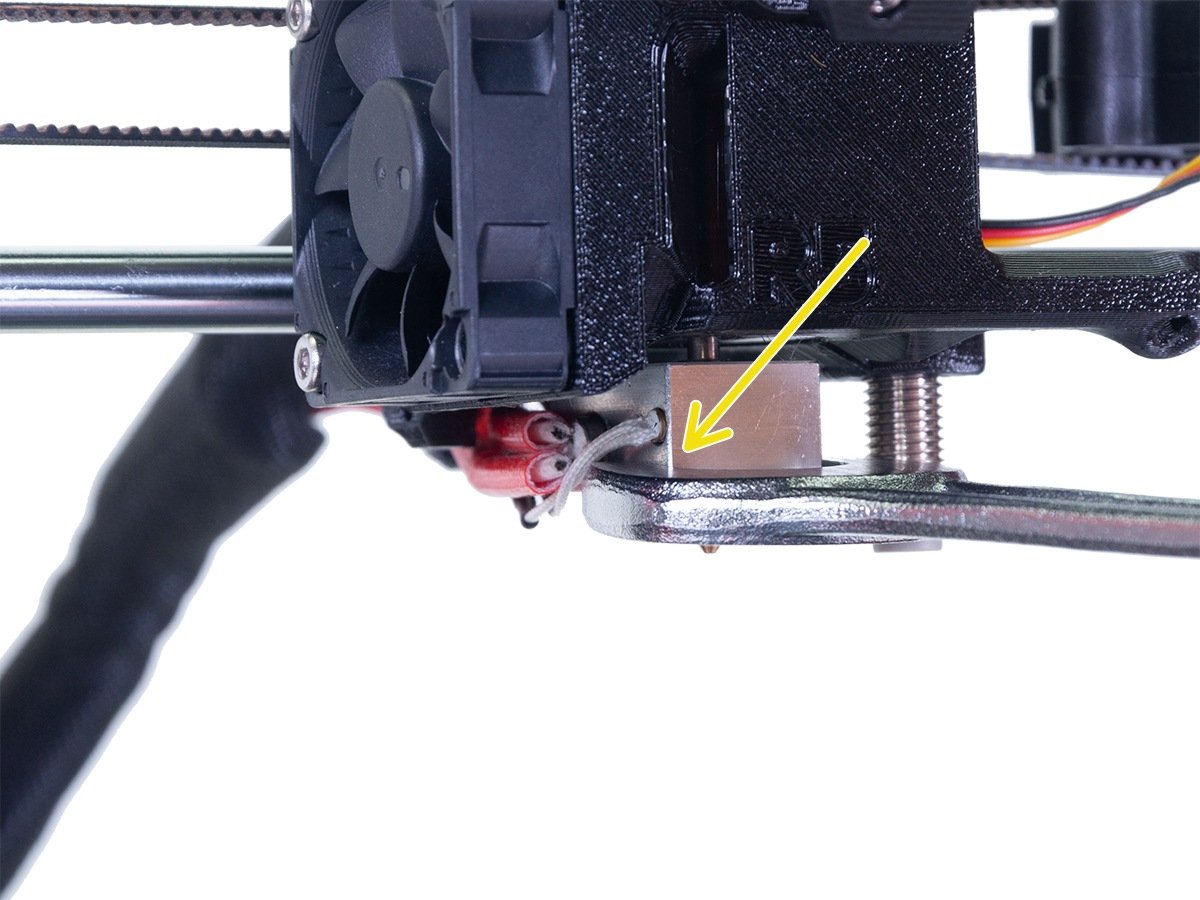
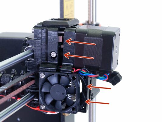
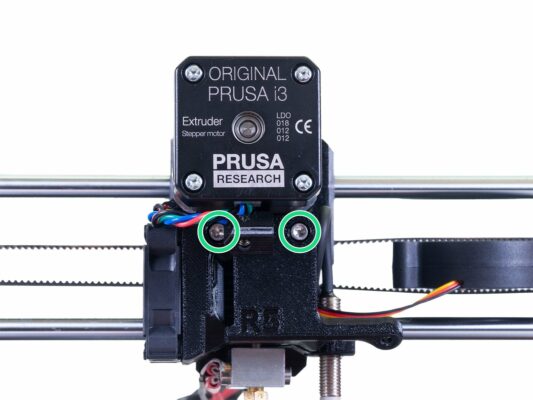
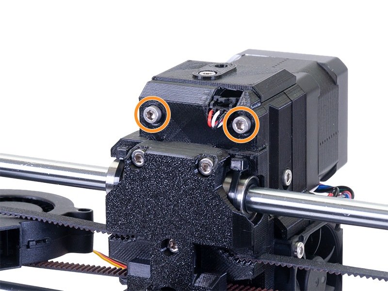
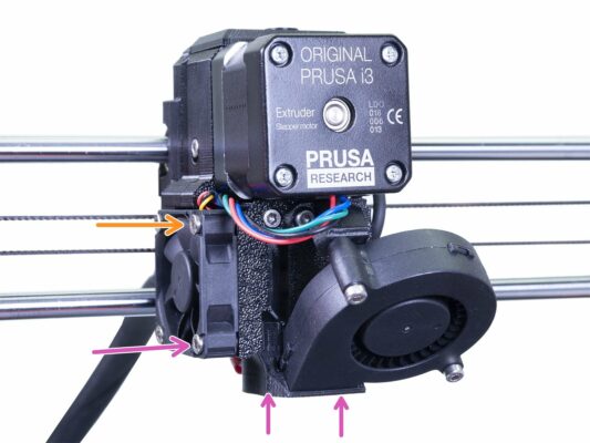
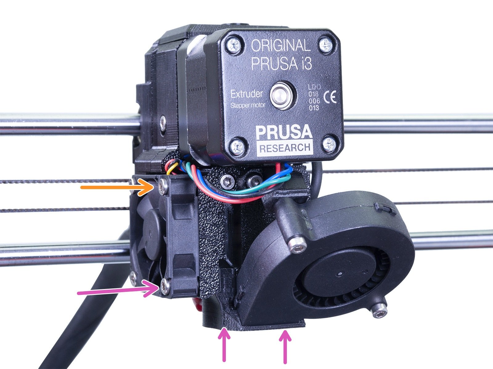
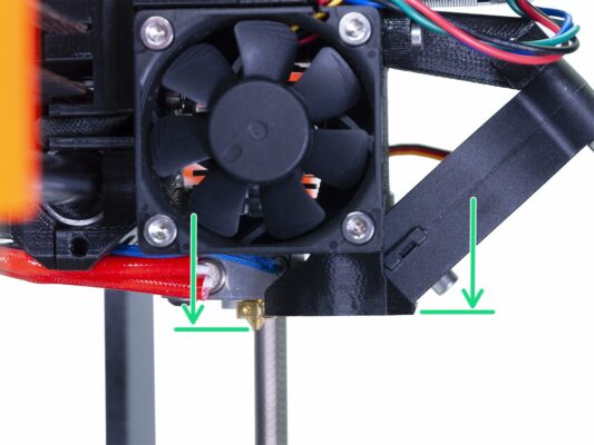
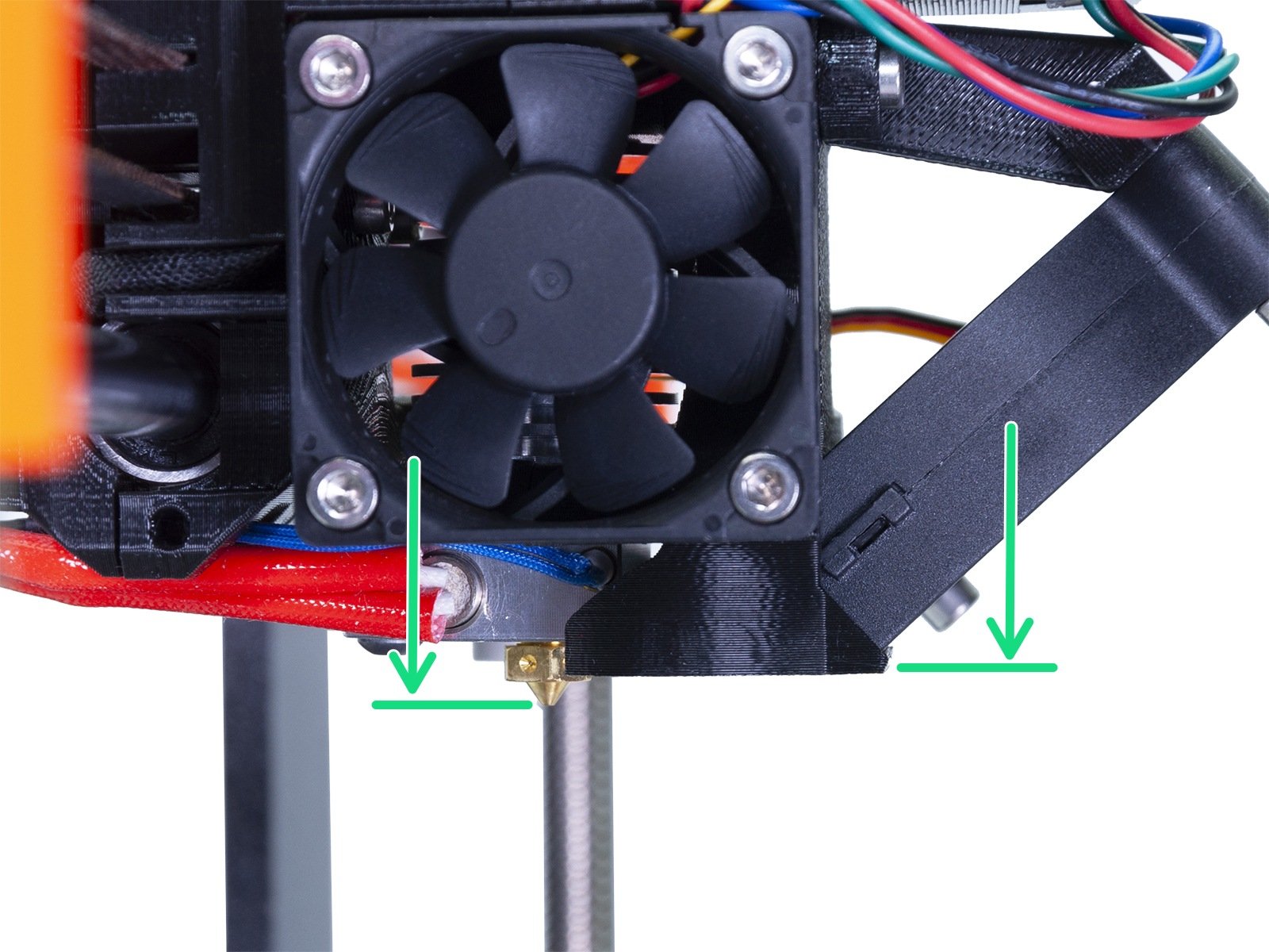
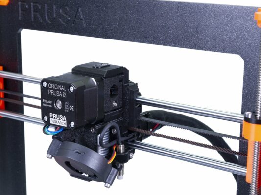
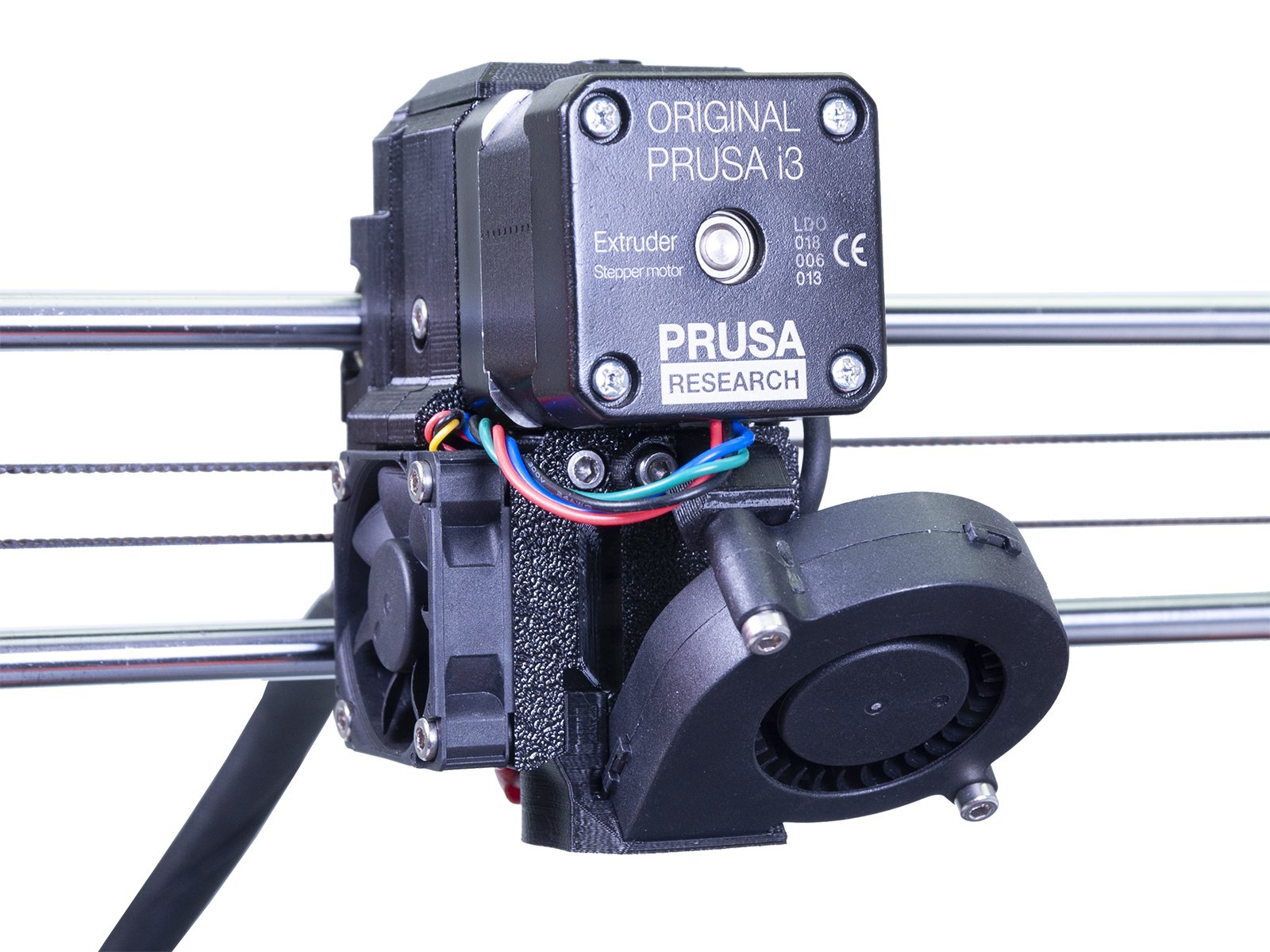
⬢IT IS CRUCIAL to ensure the hotend fits to the extruder-body!!! The printed part is shaped according to the hotend. See the second and the third picture!
If you have a question about something that isn't covered here, check out our additional resources. And if that doesn't do the trick, you can send an inquiry to [email protected] or through the button below.