JA
  • English
  • Čeština
  • Español
  • Italiano
  • Deutsch
  • Polski
  • Français
Login

7. ヒートベッドと電源ユニットの組み立て (スパイラルチューブ)

Menu

7. ヒートベッドと電源ユニットの組み立て (スパイラルチューブ)

7. ヒートベッドと電源ユニットの組み立て (スパイラルチューブ)
Relevant for:
Last updated 3 years ago
7. ヒートベッドと電源ユニットの組み立て (スパイラルチューブ)
 Difficulty
Moderate
 Steps
27
 Available languages
ENCSPLESDEITFR

Step 1 この章に必要な道具

この章に必要な道具
この章に必要な道具
作業を始める前に、正しい章をご覧頂いていることをご確認ください! もしあなたのパッケージに ケーブルスリーブ が含まれている場合には、この章の新しいバージョンに進んでください。https://help.prusa3d.com/en//Guide/7.+Heatbed++%26+PSU+assembly+%28textile+sleeve%29/589?lang=en
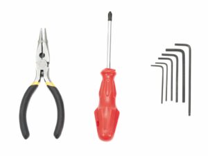
ナイロンの切断に使用するラジオペンチ
M3 ネジ 向けの 2.5mm 六角レンチ
ヒートベッド位置合わせ用の 2mm 六角レンチ

Step 2 ヒートベッドケーブルカバー を準備する (新デザイン)

ヒートベッドケーブルカバー を準備する (新デザイン)
M3n ナット をプリント部品に差し込みます。
もし M3n ナットが入らなくても、力をかけて押し込まないようにご注意ください。この場合には、M3 ネジを使って、プリント部品の反対側からねじこんでみてください。ネジを締めるにしたがって、ナットが入っていきます。締めつける際には、プリント部品を壊してしまうことのないよう、充分に気を付けながら作業を行ってください。
Old design: start with the Step 11
Extra fasteners needed for the redesigned heatbed cable cover are included with the printed part.

Step 3 スパイラルチューブの固定 (新デザイン)

スパイラルチューブの固定 (新デザイン)
以下のステップに向けて、下記の部品を用意してください。
サーミスターのケーブルが、プリント部品の中心にある切り欠きを通っていることを確認してください!!! 正しく取り付けられていない場合、ケーブルを潰してしまい、断線させてしまう可能性があります!!! (1枚目 の写真の左上をご参照ください。)
2本 の M3x10 ネジ を差し込み、締めこみます。この作業は慎重に行い、それぞれのネジは均等に締めこんでください。
片方のネジを完全に締めこんでから、もう片方を締めこむ、というような締めこみ方は しないでください! (2枚目の写真をご参照ください。)
正しく締めこまれたカバーは、3枚目 の写真のようになります。
準備ができましたか? 7. ヒートベッドと電源ユニットの組み立て (スパイラルチューブ) に移動してください。
Heatbed-cable-cover (1x)
NYLON filament 30cm (1x)

Step 4 正しいケーブルの管理 (旧デザイン)

正しいケーブルの管理 (旧デザイン)
正しいケーブルの管理 (旧デザイン)
正しいケーブルの管理 (旧デザイン)
正しいケーブルの管理 (旧デザイン)
黒のサーミスターの配線は、張った状態にならないようにし、ヒートベッドの下で少したわみを持った状態となるようにしてください。こうすることで、プリント中のヒートベッドの動きによって、ケーブルが引っ張られ、ヒートベッドの中心から外れてしまうことを防ぐことができます。
サーミスター の ケーブル を ヒートベッド の ヒーターケーブル の位置まで取り回し、数回巻き付けてください。(写真をご参照ください。)
Check the tip is similar to the third picture.

Step 5 ヒートベッドを取り付ける (パート 1)

ヒートベッドを取り付ける (パート 1)
Y キャリッジ を フロントプレート まで移動し、ヒートベッドを後側に置きます。
Y キャリッジ の中心に設けられている穴を探します。
穴の上に、スペーサーを設置します。
スペーサーの正確な位置は、次のステップで調整します。

Step 6 電源ユニットの準備

電源ユニットの準備
電源ユニットの準備
電源ユニットの準備
電源ユニットの準備
以下のステップに向けて、下記の部品を用意してください。
もし M3n ナットが入らなくても、力をかけて押し込まないようにしてください。この場合には、M3 ネジを使って、プリント部品の反対側からねじこんでみてください。ネジを締めるにしたがって、ナットが入っていきます。締めつける際には、プリント部品を壊してしまうことのないよう、充分に気を付けながら作業を行ってください。

Step 7 Mounting the heatbed-cable-cover (new design)

Mounting the heatbed-cable-cover (new design)
Place the heatbed-cable-cover on the heatbed to cover the soldered cables and LED.
Tighten the cover to the heatbed using M3x10 screw and Allen key. Be careful not to pinch (break) any wires from the heatbed!

Step 8 Proper cable management (new design)

Proper cable management (new design)
Do not stretch the black/white thermistor cable, leave some slack under the heatbed, so when the heatbed moves during print, the cable won't get stretched resulting in disconnection from the centre of the heatbed.
Guide the black thermistor cable next to the heatbed heater cable and wrap it few times around (see the photo).
The thermistor cable is in black or white colour, their functionality is the same.

Step 9 Wrapping the heatbed cables (new design)

Wrapping the heatbed cables (new design)
Use the spiral wrap and wrap the cables from the heatbed including the NYLON. Start by one or two wraps 1 cm behind the heatbed cover.
When the first wrap is ready, slide it inside the heatbed cover. Ensure it is at least 5-6 mm.
Continue with wrapping the spiral wrap.
DO NOT cut the filament, you'll need the full length.

Step 10 Securing the spiral wrap in place (new design)

Securing the spiral wrap in place (new design)
Place second part of the cover on the top of the spiral wrap.
Make sure the thermistor cable is in the middle going through a cutout in the printed part!!! Otherwise, you will pinch and possibly break the cable!!! (see the first picture top left corner)
Insert two screws M3x10 and tighten them, proceed with caution and tighten both screws equally.
Don't tighten the screw completely on one side and then on the other (see the second picture)!
Your tightened cover should look like the last picture.

Step 11 Preparing the heatbed (old design)

Preparing the heatbed (old design)
以下のステップに向けて、下記の部品を用意してください。
Heatbed MK52 (1x)
Spiral wrap (1x)
There are two spiral wraps remaining, use the bigger (thicker) one. You have to fit inside more cables now.
M3n nut (1x)
M3x10 screw (1x)
Heatbed-cable-cover (1x)
NYLON filament 30cm (1x)

Step 12 Preparing the NYLON filament (old design)

Preparing the NYLON filament (old design)
For this step please use the shorter one and DON'T TRIM it!
Using the pliers cut one end of the filament to create a tip.
Check the tip is similar to the third picture.

Step 13 Inserting the NYLON filament (old design)

Inserting the NYLON filament (old design)
Push the filament in the hole in the heatbed-cable-cover.
BE EXTREMELY CAREFUL as the pliers tends to slide and you can easily harm yourself or break the printed part!!!
To make your assembly easier, check the filament is curved up (as in the picture).
If you have issues, try to adjust the tip on the NYLON filament.

Step 14 Preparing the heatbed-cable-cover (old design)

Preparing the heatbed-cable-cover (old design)
Insert M3n nut in the printed part.
もし M3n ナットが入らなくても、力をかけて押し込まないようにしてください。この場合には、M3 ネジを使って、プリント部品の反対側からねじこんでみてください。ネジを締めるにしたがって、ナットが入っていきます。締めつける際には、プリント部品を壊してしまうことのないよう、充分に気を付けながら作業を行ってください。

Step 15 Mounting the heatbed-cable-cover (old design)

Mounting the heatbed-cable-cover (old design)
Place the heatbed-cable-cover on the heatbed to cover the soldered cables and LED.
Tighten the cover to the heatbed using M3x10 screw and Allen key. Be careful not to pinch (break) any wires from the heatbed!
The thermistor cable is in black or white colour, their functionality is the same.

Step 16 Proper cable management (old design)

Proper cable management (old design)
Do not stretch the black thermistor cable, leave some slack under the heatbed, so when the heatbed moves during print, the cable won't get stretched resulting in disconnection from the centre of the heatbed.
Guide the black thermistor cable next to the heatbed heater cable and wrap it few times around (see the photo).

Step 17 Wrapping the heatbed cables (old design)

Wrapping the heatbed cables (old design)
Use the spiral wrap and wrap the cables from the heatbed including the NYLON. Start by one or two wraps 1 cm behind the heatbed cover.
When the first wrap is ready, slide it inside the heatbed cover.
Continue with wrapping the spiral wrap.
DO NOT cut the filament, you'll need the full length.

Step 18 Securing the spiral wrap in place (old design)

Securing the spiral wrap in place (old design)
Place a zip tie around the heatbed cover to tighten the spiral wrap with cables. There is a channel around the cover designed for the zip tie.
Tighten the zip tie, but do not overtighten it! You might pinch (break) the heatbed wires. It should be snug around the stem of the cover, enough to hold the wrap in place.
Cut the remaining part of the zip tie.

Step 19 Preparing the heatbed screws and spacers

Preparing the heatbed screws and spacers
以下のステップに向けて、下記の部品を用意してください。
M3x14b screw (9x) / M3x12b screw (9x)
Due to update in manufacturing process, your kit might come with 12mm screws instead of 14 mm. Functionality remains unchanged.
6x6x3t spacer (9x)

Step 20 Mounting the heatbed (part 1)

Mounting the heatbed (part 1)
Push the Y-carriage to the front and place the Heatbed behind.
Locate a hole the centre of the Y-carriage.
Place one spacer on the top of the hole.
The exact position of the spacer will be adjusted in the next step.

Step 21 Mounting the heatbed (part 2)

Mounting the heatbed (part 2)
Push the Allen key through the middle hole on the Heatbed and place it above the spacer. Use the Allen key to align all parts.
After the alignment insert the M3x12b(14b) screw instead.
Tighten the screw just slightly.

Step 22 Mounting the heatbed (part 3)

Mounting the heatbed (part 3)
Move to the right side of the heatbed.
Place another spacer with the pliers.
Push the pliers between the heatbed and the Y-carriage.
Use the Allen key to align the spacer.
After the alignment insert the screw instead and tighten it slightly.

Step 23 Mounting the heatbed (part 4)

Mounting the heatbed (part 4)
Using pliers insert spacers and screw into the remaining holes. DON'T fully tighten the screws.
After all screws are in place, tighten them in the following order:
Center screw
First four screws
Last four screws

Step 24 Preparing the PSU

Preparing the PSU
Preparing the PSU
以下のステップに向けて、下記の部品を用意してください。
24V Power supply with cover (1x)
M4x10r screw with dome head (2x)
M3x10 screw (2x)

Step 25 Assembling the PSU (part 1)

Assembling the PSU (part 1)
Locate four mounting points on the YZ frame.
Place the PSU on the frame and secure it with the M4x10r screws. Don't tighten them completely.

Step 26 Assembling the PSU (part 2)

Assembling the PSU (part 2)
Slide the PSU holders under the PSU cover.
Secure the PSU with two M3x10 screws. Don't tighten them completely. You want to be able to move the PSU on the mount to properly line up the other mount.
Re-seat the PSU and then tighten all four screws.
Was this guide helpful?

Comments

Still have questions?

Still have questions?

If you have a question about something that isn't covered here, check out our additional resources.
And if that doesn't do the trick, you can send an inquiry to [email protected] or through the button below.

Contact us