日本語
Login
3Dプリンター
マテリアル
部品 & アクセサリー
法人向け
ソフトウェア
3Dモデル
コミュニティ
ヘルプ
コース一覧
ブログ
会社概要
サポート
Original Prusa MK4S
Original Prusa MK4 to MK4S upgrade [進行中の翻訳] (1.01)
4. Upgrading the Nextruder | MK4S MMU3
1. MK4S MMU3
ステップ 1 / 51 (章 4 / 8)
内容
コメント
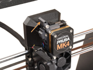
MK4/MK3.9プリンターにMMU3ユニットをご使用の場合、お使いのエクストルーダー部品の形状は若干異なります。その場合は専用のチャプターに進んでください:
⬢
4B MMU3用ネクストルーダーへのアップグレード
⬢
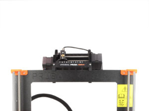
シングルマテリアルのプリンタである場合は、
次のステップに進んでください。
Loading...
次
内容
Original Prusa MK4 to MK4S upgrade [進行中の翻訳]
1. はじめに
2. Y軸のアップグレード
3. xLCDのアップグレード
4.ネクストルーダーへのアップグレード
MK4S MMU3
この章に必要な道具
ヒートベッドの保護
ネクストルーダーのカバーを外す
アイドラースイベルの取り外し
アイドラースイベルの組み立て:部品の準備
アイドラースイベルの組み立て
アイドラーナットの組み立て
ネクストルーダーケーブルの取り外し
プリントファンを取り外す
ヒートシンクとホットエンドファンの取り外し
エクストルーダーの取り外し
ギアボックス バージョン
ギアボックスのカバーを外す
エクストルーダーアイドラーの取り外し
エクストルーダーアイドラーアセンブリ:部品の準備
エクストルーダーアイドラーのアップグレード
PG-cover:部品の準備
アイドラーとPG-coverの取り付け
アイドラースイベルの組み立て:部品の準備
アイドラースイベル・アセンブリの取り付け
ネクストルーダーの組み立て:部品の準備
ネクストルーダーの組み立て
ネクストルーダーの取り付け
NTCサーミスタの接続
ホットエンドファンの組み立て:部品の準備
ホットエンドファンの組み立て
プリントファンブロワー:部品の準備
プリントファンケースの組み立て
プリントファン・ブロワーの組み立て
ファンシュラウドの組み立て
プリントファン・ブロワーアセンブリの取り付け
プリントファンブロワーの接続
Prusa CHTノズルの取り付け:部品の準備
Prusaノズルの取り外し
Prusa CHT ノズルの取り付け
ホットエンドアッセンブリーの組付け:部品の準備
ホットエンドアッセンブリーの組付け
ノズル挿入のチェック
ホットエンドケーブルの接続
ファンドアカバー:部品の準備
Fan-door-cover の取り付け
エクストルーダーケーブルの接続
LoveBoard:配線の確認
LoveBoardのカバー:部品の準備
LoveBoardをカバーする: サイドカバー
LoveBoardをカバーする: 上部カバー
残っているもの (part 1)
残っているもの (part 2)
Haribo休憩タイムです!
ネクストルーダーのアップグレード完了です!
4B.ネクストルーダーへのアップグレード(MMU3)
5. 通信関連のアップグレード
6. プリフライトの確認
マニュアルの変更ログ
コメント
ログイン
してコメントを投稿する
コメントなし