BE CAREFUL with the filament sensor, do not touch the black PCB nor the chips on it. Hold the PCB from sides.
Following assembly should be done close to the extruder, no need to pull the IR-sensor cable out. However, for a better visibility of this guide, some parts of the assembly were done separately from the printer.
MK3S/MK2.5S and MMU2S share the same new generation of the IR-sensor, just in a different position inside the extruder.
⬢You might have an IR filament sensor with black or red PCB. The red is a newer version with some hardware optimizations. Filament detection works the same on both.
First, pull the IR-sensor cable up, so you have a slack for the assembly of the printed parts. At the same time watch the other end of the textile sleeve, if you pull the cable too much, the connector will disappear in the sleeve ;)
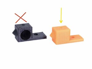
⬢Take the smaller connector WITHOUT THE SENSOR! and carefully push it all the way through the IR-sensor-holder-mmu2s.
⬢Once the connector is through, connect the cable and the sensor together.
⬢Make sure the safety latch is facing up.
⬢The sensor must be facing down.
Pictures show MK3S IR-sensor cable, but use the same procedure for the MK2.5S cable. This is valid for the entire manual.
⬢Place the entire IR-sensor assembly on top of the extruder.
⬢Align the left edge with the extruder body.
⬢Use a M3x18 screw to join both parts together.
⬢Carefully pull the cable down until the loop disappears completely. However, don't stretch the cable.
⬢M3×40 ネジ を差し込んで、センサーの組み立て を完成させます。
⬢隙間がないことを確認してください。
The IR filament sensor position will be calibrated later in the upcoming chapter. Without the proper calibration, the MMU2S won't be able to work properly.
⬢Tighten both M3x40 screws, make sure the printed parts are aligned before tightening.
⬢Tighten both M3x10 screws between the Extruder-body and X-carriage. Before you do so, ensure no cable is pinched between both parts, there is a channel in the X-carriage for all the cables.
⬢Place the Extruder-idler-mmu2s in place and secure it using a M3x40 screw.
⬢Don't tighten the screw too firmly, it serves as a shaft for the idler. Check that the idler can rotate freely (the range of the movement is small).
⬢スプリング付きの M3×40 ネジ を使用して、Extruder-idler に張力をかけます。
Hold the Extruder-idler on the other side, until the screw reaches the nut. Since there is only one screw, you need to introduce a large force. The head of the screw, should be aligned or slightly below the surface.
MK2.5S extruder differs from now on! Please use another chapter and then return here. MK2.5S extruder cable managementFollow the linked chapter to the very end, apart from the cables you need add one printed part.
⬢Use two zip ties and push them through the upper slots on the cable-holder. Add the cables from the hotend and use the channel in the printed part to arrange them properly. Tighten the zip ties, cut the remaining parts.
If you have a question about something that isn't covered here, check out our additional resources. And if that doesn't do the trick, you can send an inquiry to [email protected] or through the button below.