JA
  • English
  • Čeština
  • Español
  • Italiano
  • Deutsch
  • Polski
  • Français
Login
Menu

3B. MK3S Extruder upgrade

3B. MK3S Extruder upgrade
Relevant for:
Last updated 5 months ago
3B. MK3S Extruder upgrade
 Difficulty
Moderate
 Steps
40
 Available languages
ENCSPLDEESITFR
Tools necessary for this chapter
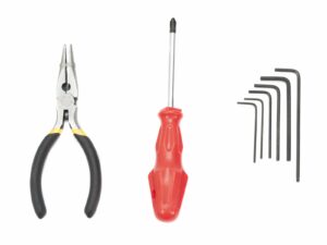
Needle-nose pliers for zip tie trimming
M3 ネジ 用の 2.5mm 六角レンチ
ナットの調整用の 2mm 六角レンチ
M2ネジ用の1.5mm 六角レンチ
はじめる前の注意事項
はじめる前の注意事項
はじめる前の注意事項
This is the most important and hardest chapter. Take your time, don't rush. Properly assembled extruder is essential.
The bag with fasteners includes M3x20 and M3x18 screws make sure you won't mix them up! Pay attention to the instructions, when to use the M3x20.
Keep the magnets a sufficient distance apart. They can damage each other!
MK3S+ 用の ホットエンド は、MK3S に比べて短い PTFEチューブ が必要です (詳細はこちら help.prusa3d.com/PTFE-MK3S+)。
Pay great attention to the cable management, if you miss some important steps you will need to disassemble the extruder.
This bag includes extra fasteners. Don't worry if you end up with a few unused screws and nuts.
Extruder-body parts preparation
以下のステップに向けて、下記の部品を用意してください。
Extruder-body (1x)
Adapter-printer (1x)
FS-lever (1x)
必要な部品リストは、次のステップにも続きます。
Extruder-body parts preparation
以下のステップに向けて、下記の部品を用意してください。
M3x18 screw (1x)
M3x10 screw (1x)
M3nS nut (2x)
M3n nut (2x)
Steel ball (1x)
Magnet 10x6x2 (1x)
Magnet 20x6x2 (1x)
Extruder-body assembly
Take the M3nS nut and insert it in the Extruder-body. Make sure the nut is all the way in.
六角レンチを使用して、ナットを正しい位置に合わせます。
Secure the nut using an M3x10 screw. Tighten the screw just slightly, later on we need to add the SuperPINDA sensor.
2本 の M3n ナット を取り、中に差し込みます。
ネジを使った引き込みテクニックを活用します。
エクストルーダー 本体 を反転させ、M3nS ナット を 1本、部品に完全に差し込みます。
小さい方の マグネット (10x6x2) を取り、慎重に FS レバー に挿入します。 マグネットの大部分は部品の内側に入り、隠れてしまいます。
FS-lever assembly
FS-lever assembly
FS-lever assembly
FS-lever を差し込みます。
Secure the part with the M3x18. Tighten it, but ensure the lever can move freely.
WARNING: make sure the following procedure is done right, otherwise the filament sensor won't work!!!
大きい方のマグネット (20x6x2) をエクストルーダー本体に挿入すると、少し先端が突き出ます。
Incorrect setup: magnets are attracting each other, thus the lever is pulled to the left.
設定が正しい場合: マグネット が互いに反発し合っているため、 レバー は右に押されています。
Steel ball assembly
Steel ball assembly
Steel ball assembly
Take the printed part Adapter-printer and insert the steel ball.
Roll with the ball to all sides to make sure it can move smoothly.
In case of any rough surface, remove the ball and clean the inside of the printed part.
Place the Adapter-printer part together with the steel ball in the Extruder-body. See the rounded protrusion on the printed part. It must fit into the groove in the Extruder-body. The top surfaces of both parts should be almost aligned.
Adapter-printer を固定するのに、ネジ を使用しないでください。それ自体が、エクストルーダー本体の内側で固定されるはずです。
Extruder motor assembly
Take the Extruder-motor-plate and secure it using two M3x10 screws. Use the cable as a guide to properly orient the part.
3 番目の ネジ は締めずに、あけておいてください。後ほど締めます。
There is a "channel" for the filament inside the printed part. Make sure the teeth on the pulley are aligned with it.
Guiding the IR-sensor cable
Make sure the IR-sensor cable does not fall out of the X-carriage-back during disassembly. If it does, follow these instructions:
IRセンサーケーブルを取り、小さい方のコネクターの端を見つけます。
Place cable in the X-carriage. Utilize the small printed overhangs to keep the cable inside.
コネクターと X キャリッジ の間の距離は 約15 mm(0.6インチ)です。 後ほど調整します。
ケーブルをスロットに通します。 このスロットを覚えておいてください、他のケーブルにも使用します。
Extruder-body assembly - parts preparation
以下のステップに向けて、下記の部品を用意してください。
MK3S+ 用 の ホットエンド (1個)
前章でホットエンドのPTFEチューブを交換したことを確認してください。MK3Sチューブは長いので、MK3S+と直接互換性がありません
M3x10 screw (2x)
M3x40 screw (1x)
Extruder-body assembly
Place the assembled Extruder-body to the X-carriage. Do not pinch the IR-sensor cable between both parts!!!
Secure it with two M3x10 screws.
Once again make sure you have replaced the hotend PTFE tube in the previous chapter! MK3S tube is not compatible with MK3S+.
Place the hotend in the Extruder-body. It must fit into the groove in the printed part, which shares the shape with the hotend.
The hotend cables should point to the left.
Extruder-body assembly
Place the assembled extruder motor on the X-carriage as seen in the picture. The motor cable must point downwards.
Hold the motor by hand and secure all parts together with the M3x40 screw. Use the right screw hole on the backside of the extruder.
Filament alignment check
もう一度ここで、フィラメント と Bondtech ギア の位置が合っているか確認しましょう。
フィラメントを上から、Bondtech を通り PTFE チューブに押し込みます。
Check the alignment and, if needed, loosen the set screw on the pulley and adjust the position. Then tighten the screw, but be careful, you can easily strip it.
REMOVE the filament.
Extruder-idler parts preparation
以下のステップに向けて、下記の部品を用意してください。
New Extruder-idler (1x)
Bondtech WITHOUT the hole for the set screw (1x)
Bearing (2x) might be stuck inside the gear
Shaft (1x)
M3n nut (1x)
M3x40 screw (1x)
Bearing assembly
Bearing assembly
Insert both bearings into the pulley. Be aware that bearings can slip out during assembly.
Extruder-idler assembly
M3n ナット を エクストルーダーアイドラー に差し込みます。
ネジを使った引き込みテクニックを活用します。
Insert the pulley into the idler as shown in the picture.
Slide the shaft through the idler and pulley. Use reasonable force or you will BREAK the printed part. The shaft should be flush with the surface of the printed part.
ベアリングがスムーズに回転することを確認してください。
Extruder-idler mounting
Extruder-idler を正しい位置に置き、M3×40 ネジ で固定します。
ネジ を強く締めすぎないでください。この ネジ はシャフトとして機能します。 アイドラーが上下自由に回転できることを確認してください。
Extruder-cover part preparation
以下のステップに向けて、下記の部品を用意してください。
Print-fan-support (1x)
M3x10 screw (1x)
M3n nut (1x)
M3x40 screw (1x)
Idler spring (1本) スプリング は ネジ に付いています
The list continues in the next step...
Extruder-cover part preparation
このステップのために、準備するもの:
Extruder-cover (1x)
M3nS nut (1x)
M3x40 screw (2x)
ナットを中に差し込んでください。
六角レンチを使用して、正しい位置に合わせてください。
今のところ、"アーム" の穴を空のままにしておきます。 プリントファンを組み立てながら、後ほど使用します。
Extruder-cover assembly
Place the Extruder-cover onto the Extruder-body. Again, make sure all three parts are properly aligned.
Insert two M3x40 screws. Tighten them, but be careful, they are slightly longer (2-3 mm) than the thickness of the entire assembly.
Take the M3n nut and insert it all the way into the Print-fan-support. It is crucial!
ネジを使った引き込みテクニックを活用します。
サポート を エクストルーダー の上に置き、傾斜した部分が "下" (ノズルに向かって) を向いているのを確認してください。
M3×10 ネジ を使用して サポート を固定します。
Pretensioning the Extruder-idler
スプリング付きの M3×40 ネジ を使用して、Extruder-idler に張力をかけます。
ネジ が ナット に達するまで、反対側の エクストルーダーアイドラー を支えておきます。
ネジは 1本しかないので、 ネジの頭が、部品の表面と一直線上になるか、もしくは表面より少し下になるくらい、しっかりと締めてください。
Hotend fan assembly - parts preparation
以下のステップに向けて、下記の部品を用意してください。
M3x14 screw (3x)
正しい ネジ を使用していることを確認してください。
Hotend fan assembly
Hotend fan assembly
Hotend fan assembly
Hotend fan assembly
Guide the extruder motor cable like in the picture. Leave some slack on the cable below the extruder motor. Leave a slack of about 2-3 cm (0.8 - 1.2 inch) below the extruder motor. This comes in handy for easier disassembly in the future.
その後、ケーブルを "スロット" に奥まで通します。
The fan has two sides, one has a sticker. Make sure, this side is facing inside the extruder.
まず、ケーブルにループを作ります。 黒い保護ラップがファンの端のラインに沿って、近いことを確認してください。 写真を参照ください。
Place the fan on the extruder and proceed in the following manner:
まず、ファンケーブルを上部スロットに押し入れます。
六角レンチ を使用して、ファン を X キャリッジ の近くにスライドさせ、ケーブル を優しく 中に押し込みます。 ファン を左に押し込む前に、ケーブルを X キャリッジ のスロット に差し込みます。
Hotend fan assembly
Hotend fan assembly
Hotend fan assembly
最終チェック! ファン はケーブルが上になるように取り付けられており、ケーブルが上部を通って X キャリッジ まで続いていることを確認してください。 X キャリッジ の両方のスロットを使用してください。途中で ケーブルが挟まれないように 注意してください!
Use the three M3x14 screws to fix the fan in place. Don't over tighten them. You can break the fan's plastic casing. Also make sure the fan can rotate freely.
この ネジ は "セルフタッピング" になっています。プリント部品内でセルフタップされており、ナットはありません。
ここでは、最後の穴はあけておきます。
Fan-shroud parts preparation
以下のステップに向けて、下記の部品を用意してください。
Fan-shroud (1x)
M3x20 screw (1x)
M3nS nut (1x)

If you have printed the fan-shroud yourself, it prints out together with the inner support which needs to be removed first.

Fan-shroud assembly
Fan-shroud assembly
Fan-shroud assembly
Fan-shroud assembly
Fan-shroudに M3nS ナット をすべて差し込みます。
六角レンチを使用して、正しい位置に合わせてください。
Fan-shroud の 出っ張り と エクストルーダー の 溝 を確認してください。
ファンシュラウド を エクストルーダー にスライドさせます。ファンシュラウド の両方の 出っ張り が エクストルーダー の 溝 に収まっていることを確認してください (写真参照) 。
Secure it using the M3x20 screw. Don't overtighten the screw, you can break the plastic casing. Also make sure the fan can rotate freely.
Print fan assembly
Print fan assembly
Print fan assembly
Print fan assembly
First, slide the fan into the Fan-shroud and make sure it is aligned properly.
次に、1本の M3×20 ネジ を使用して、ファンを所定の位置に固定します。ファンのケースを破損してしまわないように、 ネジは慎重に締め付けてください
Turn the extruder around and insert the M3n nut. No need to pull it in. We will use the screw.
もう一方の M3×20 ネジ を反対側からあて、慎重に締めていきます。ファンカバー を損傷しないように気をつけてください。
写真のように、ケーブルをスロットに入れ導き、エクストルーダーに向かって少し曲げます。ケーブルは引き延ばさないでください!
SuperPINDA センサー 部品の準備
以下のステップに向けて、下記の部品を用意してください。
SuperPINDA sensor (1x)
Note that the SuperPINDA differs from the previous generation of the PINDA sensor. Now, there are only three wires in the connector.
SuperPINDA sensor assembly
新しい SuperPINDAセンサー をホルダーに挿入してください。
センサーの半分程度をスライドさせます。後ほど、位置を調整します。
センサーからのケーブルにループを作ります。
ネジを少し締めます。完全に締め付けないでください。後で SuperPINDAセンサーの高さを調整します。
Push the cable into the channel together with the fan cable.
ナイロンフィラメントを準備する
ナイロンフィラメントを準備する
ナイロンフィラメントを準備する
ナイロンフィラメントを準備する
ナイロンフィラメントを切断する際は、 安全メガネ を着用することをお勧めします。
以下のステップに向けて、下記の部品を用意してください。
New black nylon filament 50 cm / 19.7 inch (1x)
The upgrade package includes new nylon in case yours from the disassembled printer is damaged or no longer rigid enough.
Using the pliers, cut one end of the filament to create a tip.
Check to make sure the tip is similar to the third picture.
The upgrade package includes new nylon in case yours from the disassembled printer is damaged or no longer rigid enough.
Nylon guide assembly
ナイロンフィラメントを差し込む穴を探します。一番小さい六角レンチを使って、穴の中に異物が入っていないことを確認してください。
Using the pliers insert the NYLON filament with the pointed end into the slot and twist it. Hold the extruder with your other hand.
この作業はとても慎重に行ってください!!! ラジオペンチは滑りやすく、配線を傷つけてしまうことがあります!!!
フィラメントが正しくささっているかを確認するため、手でやさしく引いてみてください。X軸 が少しだけ曲がって、フィラメントがスロットから抜けなければ正しい状態です。
もし上手くいかない場合には、フィラメントの先端を形状を調整してみてください。
IR-sensor - parts preparation
以下のステップに向けて、下記の部品を用意してください。
M2x8 screw (1x)
New Prusa IR-sensor (1x)
Make sure you have prepared the red version of the IR-sensor. You can use the red IR-sensor you had on your printer before and keep the new one from the package as a spare. Do not use the old (black) version of the sensor!
FS-cover (1x)
M3x10 screw (1x)
IR-sensor assembly
IR-sensor assembly
IR-sensor assembly
IR-sensor assembly
IR センサー を エクストルーダー 本体の上に置き、M2x8 ネジ で固定します。黒いプラスチックの "U字型" 部分が、下を向いていることを確認してください。
Tighten the M2x8 screw, the sensor shouldn't be able to move - but be careful the PCB isn't indestructible ;)
Connect the cable. Mind the correct orientation of the connector and wires.
Leave some slack behind the sensor like in the picture. Don't create too big cable loop as it might interfere with the frame. Adjust the length by gently pulling/pushing the cable if needed.
Place the FS-cover on the extruder and align it according to the picture. Tapered sides of the cover must be oriented towards you.
ネジ を正しい穴に入れ(写真参照)、締め込みます。
ヒント: ナットに手が届かない場合は、六角レンチを使用してナットを揃えるか、スペアバッグからより長いネジを使用してナットを引き上げます。
X-carriage-back assembly
以下のステップに向けて、下記の部品を用意してください。
M3x10 screw (4x)
Zip tie (5x)
New textile sleeve 13 x 490 mm (1x)
The upgrade package includes a new textile sleeve in case yours from the disassembled printer is damaged.
Mounting the X-carriage-back
Push the SuperPINDA sensor cable and the nylon filament through the opening in the x-carriage-back.
エクストルーダーをXキャリッジに戻します。
M3x10ネジ4本を使用して固定します。
ケーブルスリーブを取り付ける
ケーブルスリーブを取り付ける
ケーブルスリーブを取り付ける
ケーブルスリーブを取り付ける
ケーブルスリーブの片側を開き、エクストルーダーにつながっているケーブル束に被せます。
ホットエンドのケーブルについては、被せずにそのままにしておきます。
最初の 1巻き は cable-holder よりも若干長いくらいが適切です。5 cm ほどあれ十分です。
Gently twist the sleeve to make it smaller and tighter around the cables. Orient the sleeve's seam downwards, then slide the sleeve towards the extruder.
3本 の 結束バンド を cable-holder の 低い方の列 の穴に差し込みます。
スリーブをもう一度ねじって(中のケーブルをねじらないように)、結束バンドを締めます。
重要: それぞれ結束バンドの残り部分は、できるだけ先端に近いところでペンチを使って切断します。 結束バンドの先端の位置が正しいことを確認してください(少し左にずれています)。
ケーブルスリーブを取り付ける
ケーブルスリーブを取り付ける
ケーブルスリーブを取り付ける
ケーブルスリーブを取り付ける
ケーブルホルダー上部のスロットに、2本 の結束バンドを差し込みます。
注意! 結束バンドのループを作る前に、ホットエンドからのケーブルが巻き込まれるようにします。プリント部分のチャネルを使用して、正しく配置します。
ホットエンドのケーブルが正しく通ることを確認しながら、結束バンドを締めこみ、余分な部分を切断します。
ケーブルスリーブを開き、ホットエンドにつながっているケーブルを差し込みます。
まとめたケーブルと 最後の写真を比較してみてください。
E-axis is finished!
E-axis is finished!
もう少しです、頑張っていきましょう!
最終的な仕上がりを写真と比較しながら確認します。
It is time for the next chapter: 4. Electronics assembly.
Was this guide helpful?

Comments

Still have questions?

Still have questions?

If you have a question about something that isn't covered here, check out our additional resources.
And if that doesn't do the trick, you can send an inquiry to [email protected] or through the button below.

Contact us