The XYZ calibration is a process, which checks, whether the printer was assembled correctly and the axes are perpendicular to each other. It measures the skew of your X/Y axis and applies compensations for any imperfections. It may indicate two sets of error messages compromised/failed. See below for a detailed description.
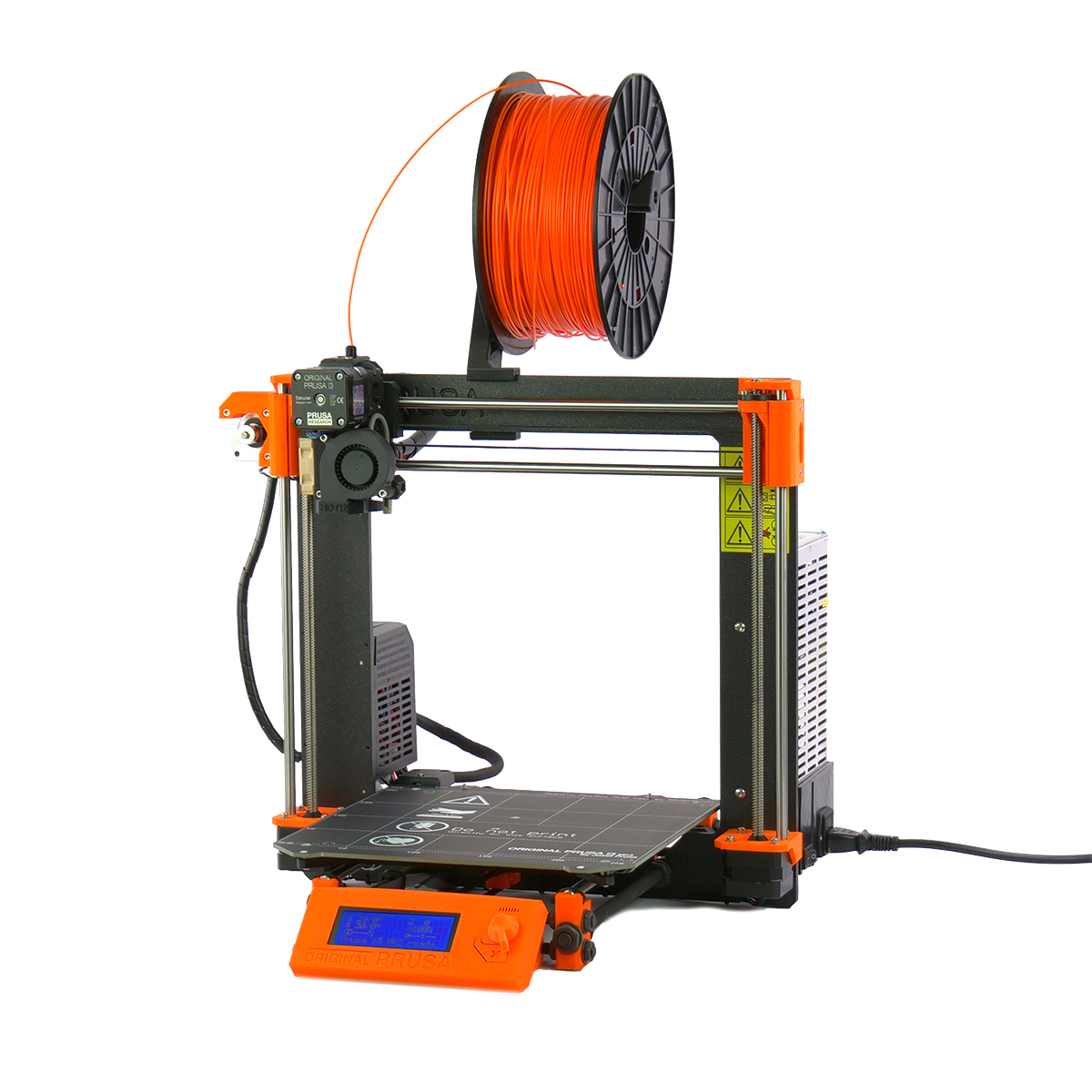 XYZ calibration is a part of the Wizard, which will appear on the first boot or after a factory reset. In case you have skipped the Wizard, you can start it manually from the LCD Menu - Calibration - Wizard.
If you wish to redo the XYZ calibration and you have finished the Selftest successfully, you can start the XYZ calibration separately through the LCD Menu - Calibration - XYZ cal.
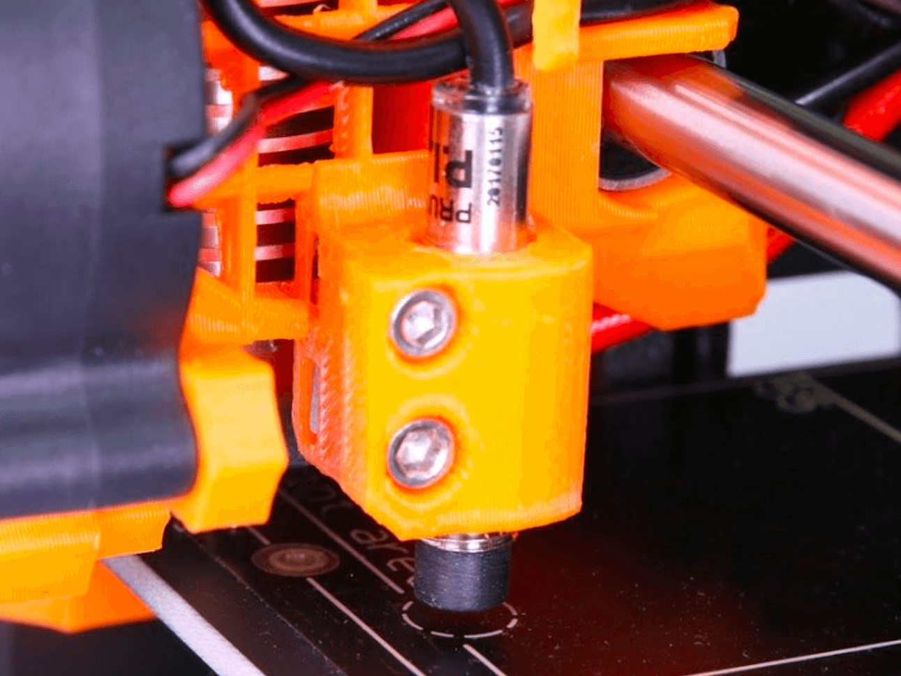
P.I.N.D.A V2 or SuperPINDA
There are several versions of our auto-leveling probe. The table below outlines their history and compatibility across the Original Prusa printers.
| Printer | Initial sensor | Replaced by |
|---|---|---|
| MK2/S | P.I.N.D.A. V1 | - |
| MK2.5 and MK2.5S | P.I.N.D.A. V2 | SuperPINDA |
| MK3, MK3S and MK3S+ | P.I.N.D.A. V2 | SuperPINDA |
- The P.I.N.D.A. V2 is black with no markings (left picture).
- The SuperPINDA has orange text on the wire, close to the probe (right picture). The SuperPINDA's connector also only has three wires, while the P.I.N.D.A. V2 has four due to its integrated thermistor.
 |  |
| P.I.N.D.A. V2 - Without markings | SuperPINDA - With markings |
Calibration walkthrough
- The printer will start the calibration by aligning the Z-axis. You spin the selector knob clockwise until both ends of the X-axis reached the top, and then one extra turn to ensure it has reached it fully. The printer will then ask if it is at the top. Select Yes.
- In the next step, the printer asks whether you have the steel sheet on the heated bed. Remove the steel sheet for the upcoming initial 4 point calibration now and select No.
- Check that the nozzle is clean and confirm the on-screen prompt.
- Place a sheet of paper (e.g. the included cheat sheet) between the nozzle and the heatbed. If the nozzle catches the paper, immediately press the Reset button. Your sensor is probably set too high. Lower it down by 2 - 3 threads and run the XYZ calibration again. More info below.
- Once the first routine finishes, place the steel sheet on the heated bed and confirm the on-screen prompt. The printer will perform a full 9 point mesh bed leveling. All of the measured compensations will be stored in non-volatile memory.
For more details on the XYZ calibration procedure's inner workings, please see the Github changelog.
Troubleshooting the XYZ calibration
If you encounter any error messages, there is most likely something wrong with the assembly of your printer.
Please perform the following tasks:
- Make sure you followed the instructions on the LCD precisely. Especially make sure that the X-axis moved to the very top. Otherwise, the Z-axis might be misaligned.
- Make sure that the cable harness leading from the extruder, or the zip ties securing it, does not hit the cover of the miniRAMBo board before it reaches the end of the X-axis.
- Make sure your belts are at the correct tension.
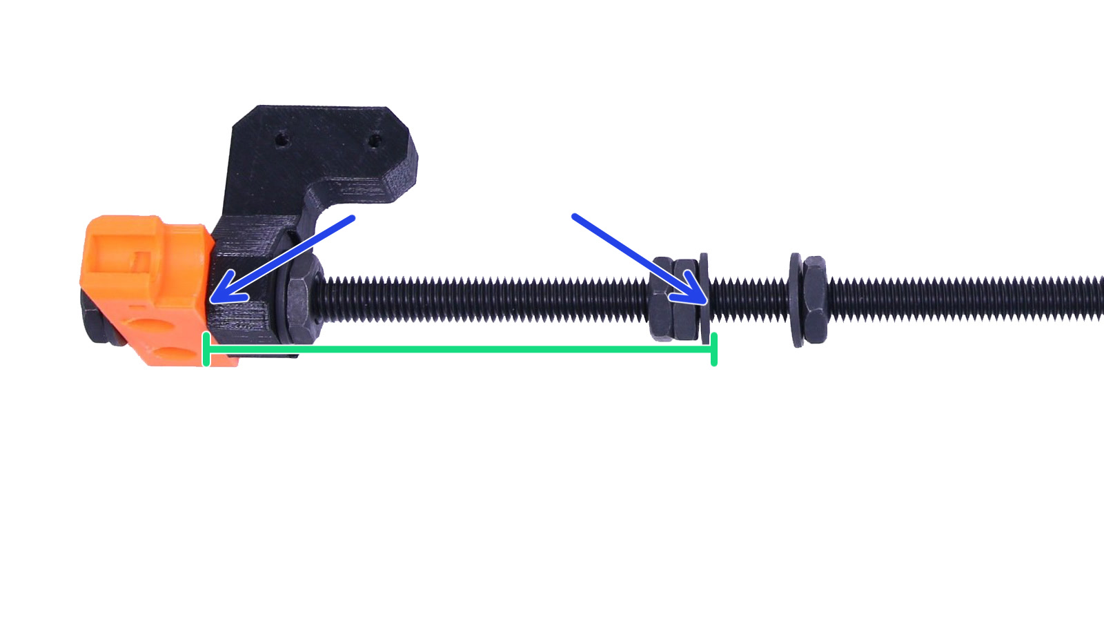
- Double-check that there's a 100mm (3.937inches) distance between the Y-corners and the frame (green ruler). The start and endpoint of this distance are indicated by the blue arrows.
- Navigate to LCD menu - Calibration - Auto-home. The P.I.N.D.A./SuperPINDA sensor must stop right in the center of the 1st calibration point (please refer to the photos below). If it does not align it may indicate an issue with the Y-corner length explained in the previous step (step 4).

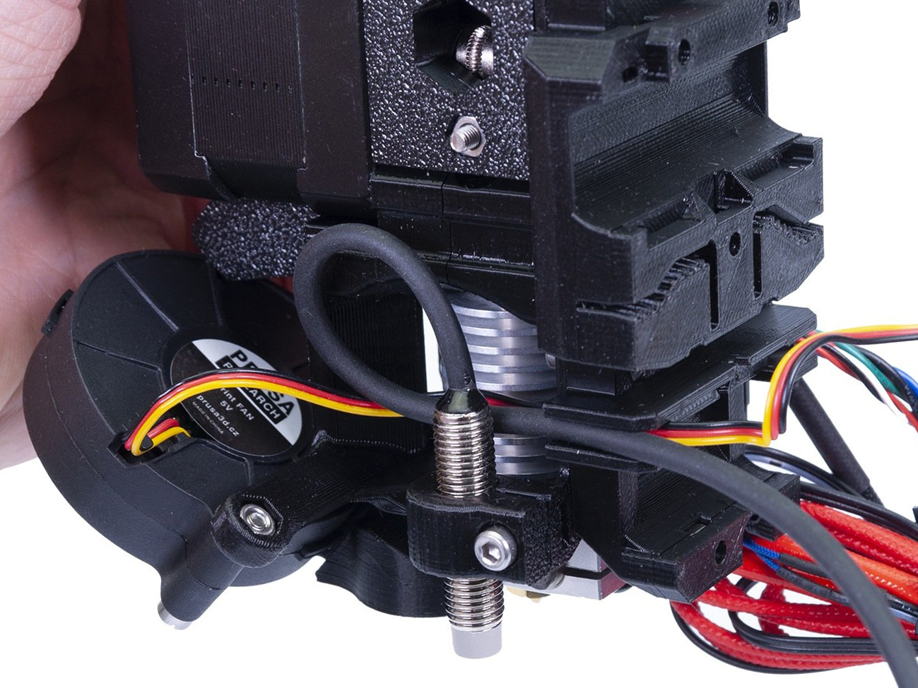
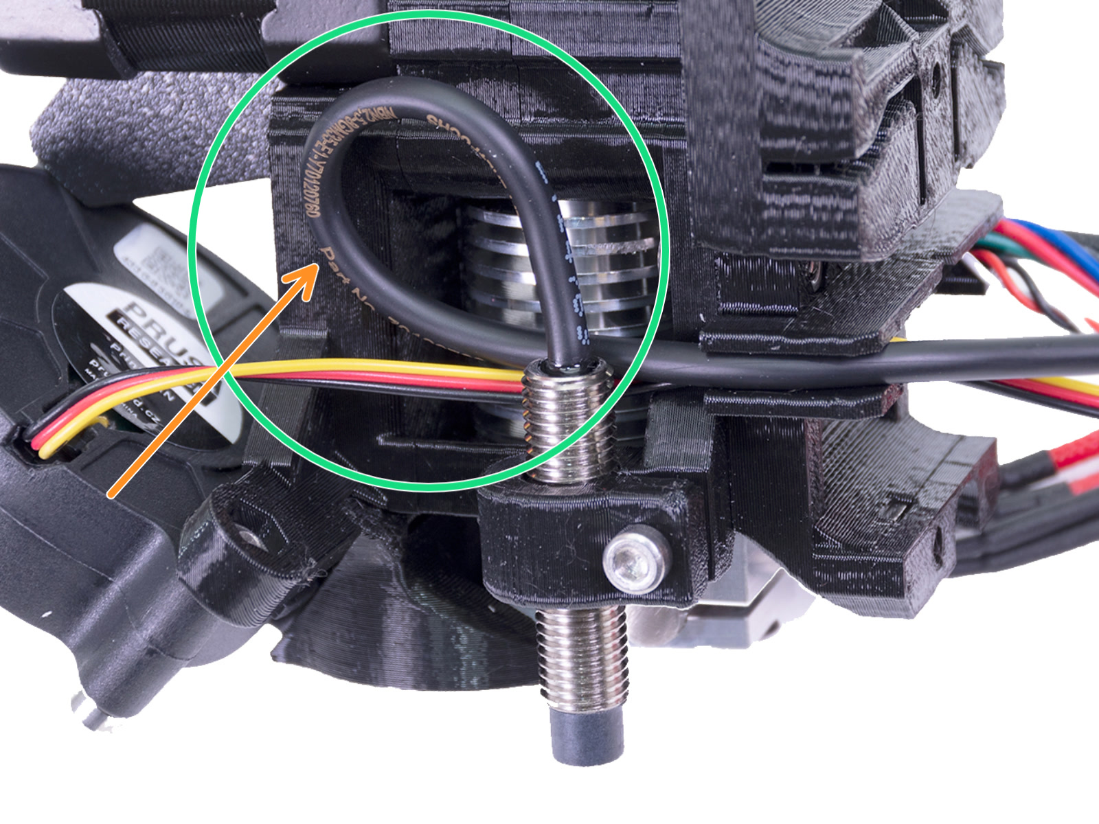
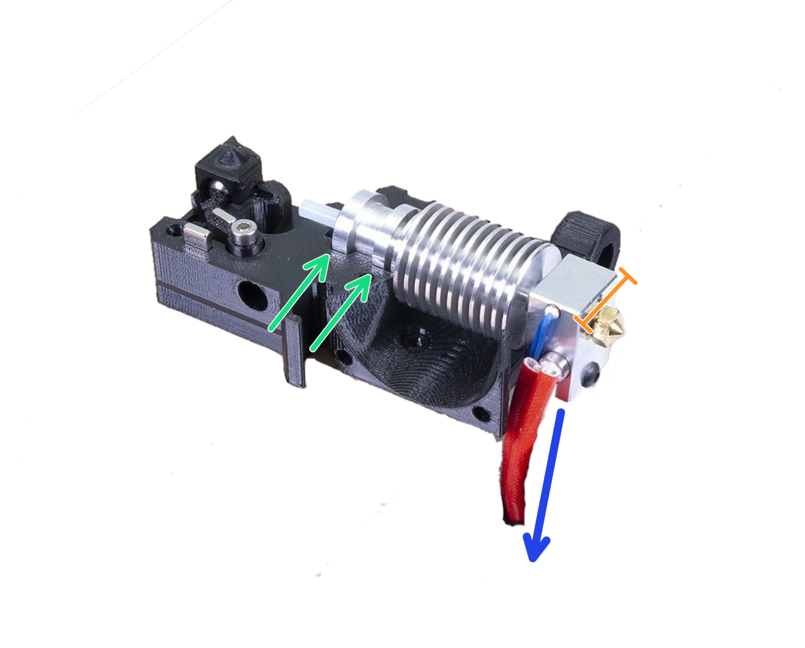
- Check the E-axis assembly. Make sure that the hotend is correctly inserted in the extruder. The heatsink must be slotted into both slots (green arrows), the short side of the heater block is facing forward (orange ruler), with its wires running back alongside the left side of the heater block (blue arrow). More info on this in Zキャリブレーションの失敗 (MK3S/MK2.5S).
- Make sure nothing blocks the movement of any of the axis. You can easily test that by moving the extruder or heatbed through LCD Menu - Settings - Move axis (X/Y). Simply move it from one end to the other and inspect the movement.
- Make sure that your P.I.N.D.A. or SuperPINDA sensor is roughly 1 mm higher than the tip of the nozzle. Distancing the sensor is covered in the assembly manual Part 6. Preflight check.

- There is also a small possibility that your P.I.N.D.A./SuperPINDA sensor could be defective. The easiest way how to check that is to navigate to LCD Menu - Support - Sensor info. While placing anything metal (e.g. a spatula) under the sensor, the "P.I.N.D.A." value should change from 0 to 1 and the light should go out. More information can be found in M.I.N.D.A./SuperPINDA センサーのテスト (MINI/MINI+).