English
Login
3D printers
Materials
Parts & Accessories
For Business
Software
3D Models
Community
Help
Courses
Blog
Company
Support
Original Prusa i3 MK3S
Original Prusa i3 MK3S kit assembly (v3.15)
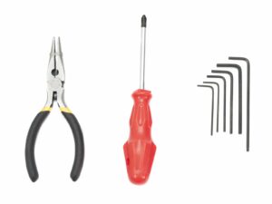
6. LCD assembly | Tools necessary for this chapter
1. Tools necessary for this chapter
Step 1 of 12 (Chapter 6 of 11)
Contents
Comments
⬢
2.5mm Allen key for M3 screws
⬢
2mm Allen key for nut alignment
Bag with fasteners for the LCD is usually taped to the LCD.
Loading...
Next
Contents
Original Prusa i3 MK3S kit assembly
1. Introduction
2. Y-axis assembly
3. X-axis assembly
4. Z-axis assembly
5. E-axis assembly
6. LCD assembly
Tools necessary for this chapter
Preparing the LCD parts
Checking the LCD cables
Assembling the LCD supports
Assembling the LCD-cover
Securing the LCD controller
Preparing the supports for assembly
Mounting the LCD display onto the printer
Assembling the LCD knob
Haribo time!
LCD is done!
Different PSU types
7. Heatbed & PSU assembly (Black PSU)
7. Heatbed & PSU assembly (Silver PSU)
8. Electronics assembly
9. Preflight check
Manual changelog
Comments
Log in
to post a comment
Wout
•
[quote]Bag with fasteners for the LCD is usually taped to the LCD.[/quote]
Excuse me?
Reply

Excuse me?