Español
Login
Impresoras 3D
Materiales
Piezas y accesorios
Para Empresas
Software
Modelos 3D
Comunidad
Ayuda
Cursos
Blog
Empresa
Soporte
Original Prusa XL
Mantenimiento de la impresora
How to replace a PSU (XL) | Comenzar el montaje
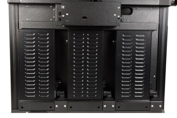
1. Comenzar el montaje
Paso 1 de 25 (Capítulo 23 de 42)
Contenidos
Comentarios
Dificultad
Moderada
Idiomas disponibles
Comenzar el montaje
Contenidos
Mantenimiento de la impresora
How to replace the CoreXY plastic parts
Cómo instalalar el Adaptador Nextruder a boquilla V6 (XL monocabezal)
Como reemplazar la boquilla Prusa (XL monocabezal)
Cómo sustituir el conjunto del Hotend (XL monocabezal)
Embalaje de la impresora para devolución - Material de embalaje original (XL)
Cómo reemplazar la boquilla Prusa (XL multicabezal)
Cómo sustituir un motor del eje Z (XL)
Embalaje de la XL Multicabezal para devolución - Material de embalaje original
Cómo sustituir un azulejo de la base calefactable y un cable del azulejo (XL)
Cómo reemplazar un ventilador de impresión (XL de un cabezal)
How to fix Modular bed error (HW solution)
Como reemplazar las tuercas trapezoidales (XL)
Cómo limpiar el sensor de filamento lateral (XL)
Cómo cambiar el xLCD y el cable del xLCD (XL monocabezal)
Cómo reemplazar la placa Dwarf (XL multicabezal)
How to replace Nextruder heatsink (XL Multi-tool)
Cómo reemplazar la placa Dwarf (XL monocabezal)
Cómo sustituir el conjunto del Hotend (XL multicabezal)
Como reemplazar un termistor del fusor (XL monocabezal)
Cómo sustituir una guía lineal del eje Z (XL)
Cómo reemplazar el inserto del perfil (XL)
How to replace the hotend fan (XL Multi-tool)
Cómo reemplazar una fuente de alimentación (XL)
Comenzar el montaje
Introducción
Herramientas necesarias
Preparación de la impresora
Retirando el middle-rear-panel
Desmontaje de la tapa del interruptor
Retirando la cubierta de la fuente de alimentación
Retirando los cables de la fuente de alimentación (izquierda)
Retirando los cables de la fuente (medio)
Retirando los cables de la fuente de alimentación (derecha)
Retirando la fuente de alimentación del marco.
Sustitución de la fuente de alimentación - preparación de las piezas
Cubiertas fuente de alimentación - preparación de piezas
Preparando la fuente de alimentación
Montando la upper-cover-mount de la fuente de alimentación
Asegurando la fuente de alimentación a la estructura
Conexión de los cables de la fuente de alimentación izquierda (CRÍTICO) - parte 1
Conexión de los cables de la fuente de alimentación izquierda (CRÍTICO) - parte 2
Conectando los cables de la fuente de alimentación central (CRÍTICO)
Conectando los cables de la fuente de alimentación derecha (CRÍTICO)
Montando la cubierta
Montando la cubierta de la fuente de alimentación
Montaje del middle-rear-panel
Probando la impresora
¡Buen trabajo!
Como reemplazar un calentador del fusor (XL Mono Cabezal)
Cómo lubricar los pasadores de acoplamiento de la Original Prusa XL (MultiCabezal)
How to replace the tch-profile-insert (XL)
Cómo reemplazar la Placa Sandwich (XL)
Cómo reemplazar la goma elástcia en la Original Prusa (XL multicabezal)
Como reemplazar la Cubierta Trasera CoreXY (Original Prusa XL)
Cómo instalalar el Adaptador Nextruder a boquilla V6 (XL Multi Cabezal)
How to replace a XY motor (XL)
Packing the XL Enclosure for return - Original Packing material
How to change the belt (XL)
Cómo sustituir la cubierta del conector del cable principal (XL)
How to replace the PDU splitter (XL)
Cómo reemplazar un ventilador de impresión (XL multi cabezal)
Como reemplazar las tuercas trapezoidales (XL)
How to lubricate linear bearing rails (XL)
How to change the xLCD (XL)
How to set up a Buddy3D Cam
How to replace Nextruder heatsink (XL Single-tool)
Como reemplazar un Nextruder (XL de un cabezal)
Comentarios
Inicia sesión
para publicar un comentario
Sin comentarios