Español
Login
Impresoras 3D
Materiales
Piezas y accesorios
Para Empresas
Software
Modelos 3D
Comunidad
Ayuda
Cursos
Blog
Empresa
Soporte
Original Prusa MINI+
Original Prusa MINI Enclosure (1.0)
Fire Suppression System (add-on) | Herramientas necesarias para este capitulo
1. Herramientas necesarias para este capitulo
Paso 1 de 15 (Capítulo 6 de 8)
Contenidos
Comentarios
⬢
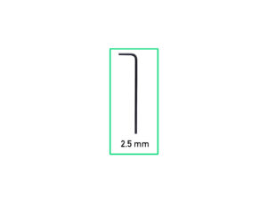
Para este capítulo, prepara por favor:
⬢
Llave Allen de 2.5mm
Loading...
Siguiente
Contenidos
Original Prusa MINI Enclosure
1. Introducción
2. Ensamblando el cerramiento
3. Instalando la impresora
Sistema de filtración avanzado (complemento)
Tira LED blanca (complemento)
Sistema de Extinción de Incendios (complemento)
Herramientas necesarias para este capitulo
Desmontaje del brazo lateral
Desconectando los cables
Desinstalando la impresora
Sistema de Extinción de Incendios: preparación de las piezas
Montaje de la abrazadera en P
Montaje de la abrazadera en P
Instalando el sistema automático de supresión
Asegurando el sistema automático de supresión
Instalando la impresora
Ajustando la posición de la impresora
Conectando los cables
Montaje del brazo lateral
Conectando los cables
Eso es todo
Cerradura mecánica (complemento)
Registro de cambios del Manual del kit de MINI Enclosure
Comentarios
Inicia sesión
para publicar un comentario
Sin comentarios