Español
Login
Impresoras 3D
Materiales
Piezas y accesorios
Para Empresas
Software
Modelos 3D
Comunidad
Ayuda
Cursos
Blog
Empresa
Soporte
Original Prusa MINI+
Original Prusa MINI Enclosure (1.0)
Advanced filtration system (add-on) | Herramientas necesarias para este capitulo
1. Herramientas necesarias para este capitulo
Paso 1 de 42 (Capítulo 4 de 8)
Contenidos
Comentarios
⬢
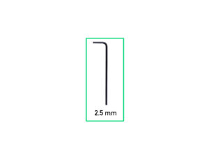
Para este capítulo, prepara por favor:
⬢
Llave Allen de 2.5mm
Loading...
Siguiente
Contenidos
Original Prusa MINI Enclosure
1. Introducción
2. Ensamblando el cerramiento
3. Instalando la impresora
Sistema de filtración avanzado (complemento)
Herramientas necesarias para este capitulo
Herramientas adicionales
Piezas opcionales
Desmontaje del brazo lateral
Desconectando los cables
Desinstalando la impresora
Sistema de filtración avanzada: Preparación de las piezas
Montaje de la filtración: preparación de las piezas
Montaje de la filtración
Montaje de la filtración
Montaje de la filtración
Instalando el ventilador
Instalando el filtro HEPA
Instalando el filtro HEPA
Instalando la filtración
Guiado del cable de la filtración: preparación de las piezas
Guiado de los cable del complemento: cable filtración
Fuente de alimentación: preparación de las piezas
Soltando el pie trasero
Guiando el cable de la fuente de alimentación
Asegurando el pie trasero
Soltando el pie delantero
Asegurando el cable de la fuente
Placa básica: preparación de las piezas
Instalando la Placa básica
Instalando la Placa básica
Montaje de la Placa básica
Conectando la Placa básica
Aclaración sobre el soporte de la fuente de alimentación (opcional)
Soporte de la fuente: preparación de las piezas (opcional)
Preparación tuerca del soporte de la fuente de alimentación (opcional)
Preparación del soporte de la fuente de alimentación (opcional)
Colocando el soporte de la fuente de alimentación (opcional)
Asegurando la fuente de alimentación (opcional)
Instalando la impresora
Ajustando la posición de la impresora
Conectando los cables
Montaje del brazo lateral
Conectando los cables
Conectando las fuentes: preparación de las piezas
Conectando las fuentes
Eso es todo
Tira LED blanca (complemento)
Sistema de Extinción de Incendios (complemento)
Cerradura mecánica (complemento)
Registro de cambios del Manual del kit de MINI Enclosure
Comentarios
Inicia sesión
para publicar un comentario
Sin comentarios