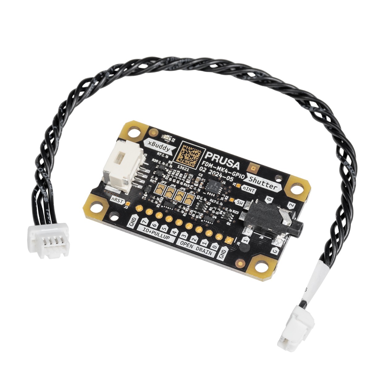
El módulo GPIO (General Purpose Input Output) es una PCB adicional y opcional que puede conectarse a la Prusa CORE One/+, y a la Original Prusa MK4/S, MK3.9/S o MK3.5/S.
El módulo ofrece una funcionalidad ampliada al permitir el control de dispositivos externos mediante conexiones a los pines GPIO de la placa, que pueden funcionar en modo de ENTRADA o SALIDA. Esta versatilidad abre un amplio abanico de posibles casos de uso.
Comparte y debate tus proyectos con los demás miembros de la Comunidad Prusa en nuestro foro oficial. Hemos creado una sección dedicada a la GPIO.
Ideas de casos prácticos
El módulo puede controlar el obturador de una cámara en un momento preciso, por lo que es ideal para crear time-lapses visualmente perfectos, en los que cada imagen se captura exactamente en el mismo punto en el tiempo.
Además de controlar el obturador de una cámara, el módulo puede utilizarse para otras aplicaciones. Por ejemplo, puede activar la iluminación externa para iluminar la zona de impresión en fases específicas del proceso de impresión, garantizando unas condiciones de iluminación óptimas para las comprobaciones de calidad o la toma de fotografías. Además, puede configurarse para activar ventiladores de refrigeración u otros dispositivos periféricos, como extractores o alarmas, en función de la ejecución de códigos G personalizados durante las impresiones, lo que ayuda a mantener unas condiciones de funcionamiento óptimas y a mejorar la seguridad y eficacia del entorno de impresión 3D.
Otro potente caso de uso es la integración de un teclado de macros, en el que cada pulsación de tecla puede desencadenar la ejecución de comandos de Código G específicos. Esta configuración permite un rápido control manual de las funciones de la impresora, como iniciar o pausar una impresión, ajustar la temperatura o mover el cabezal de impresión a una posición exacta. La posibilidad de activar acciones personalizadas con una simple pulsación de tecla puede agilizar considerablemente los flujos de trabajo, lo que convierte al módulo de expansión GPIO en una herramienta versátil e indispensable para quienes desean personalizar y optimizar al máximo su configuración de impresión 3D..
¡La seguridad lo primero!
Aunque la posibilidad de activar el Código G a través de entradas GPIO aporta una gran flexibilidad, también conlleva limitaciones y riesgos potenciales. Un uso inadecuado o una mala sincronización de los comandos G-Code pueden interferir en el proceso de impresión, provocando fallos de impresión o incluso daños en la impresora. Es crucial probar a fondo cualquier configuración personalizada de Código G en un entorno controlado antes de implementarla en trabajos de impresión reales para evitar consecuencias no deseadas.
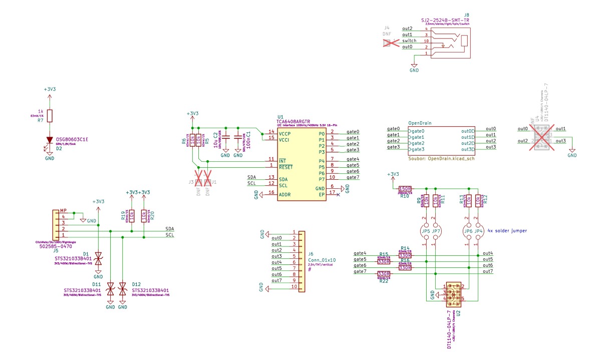
Esquemas
Los esquemas son de código abierto y están disponibles en nuestra página Open Source en Prusa Research.
Cómo instalar la placa GPIO
- Asegúrate de que la impresora esta fría a temperatura ambiente y apáguela.
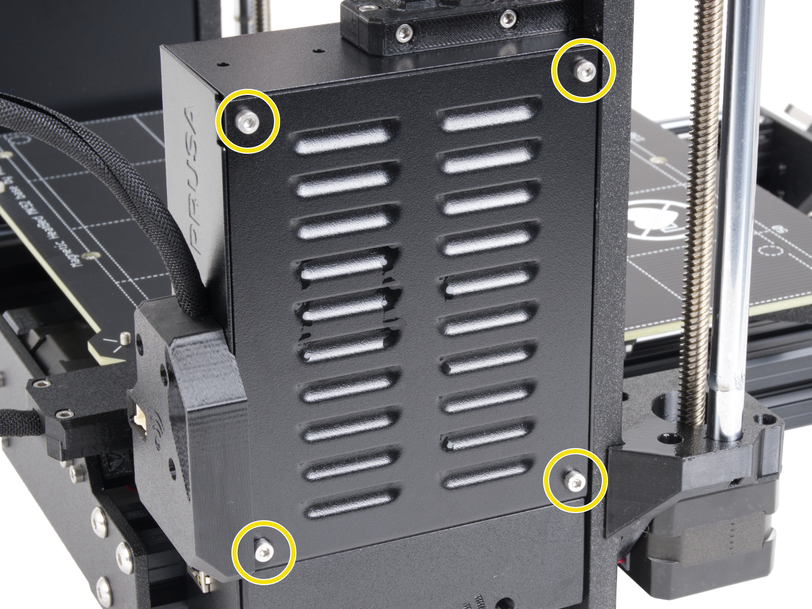
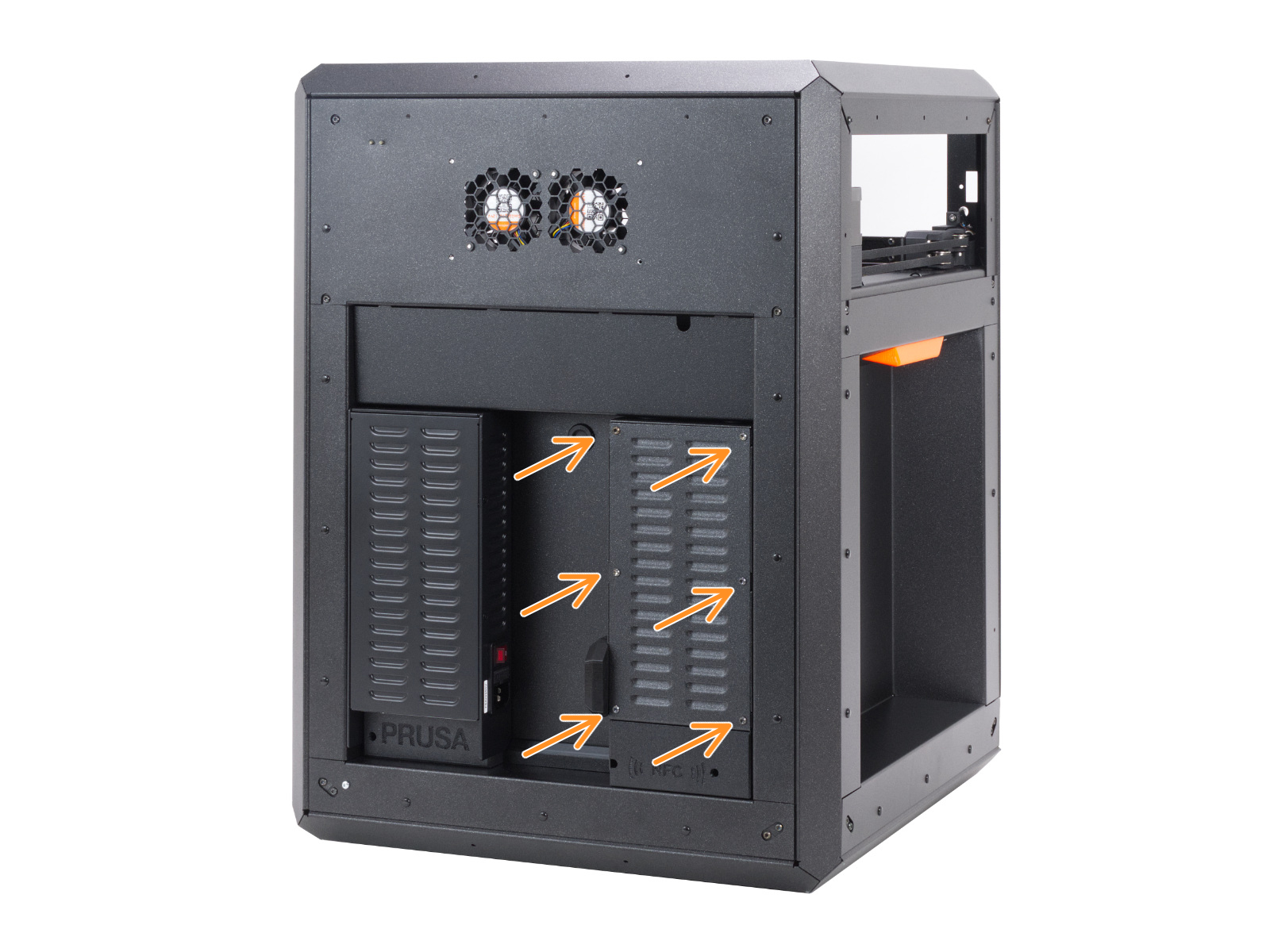
- Open the xBuddy box cover by removing four M3x6 screws (MK-series), by removing six M3x4bT bolts (CORE One).
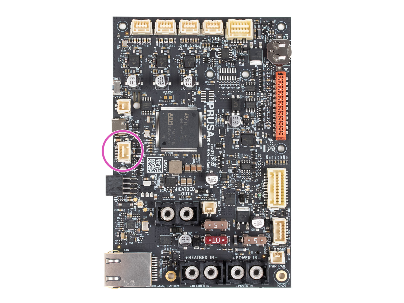
- Conecta el cable GPIO al puerto I2C.
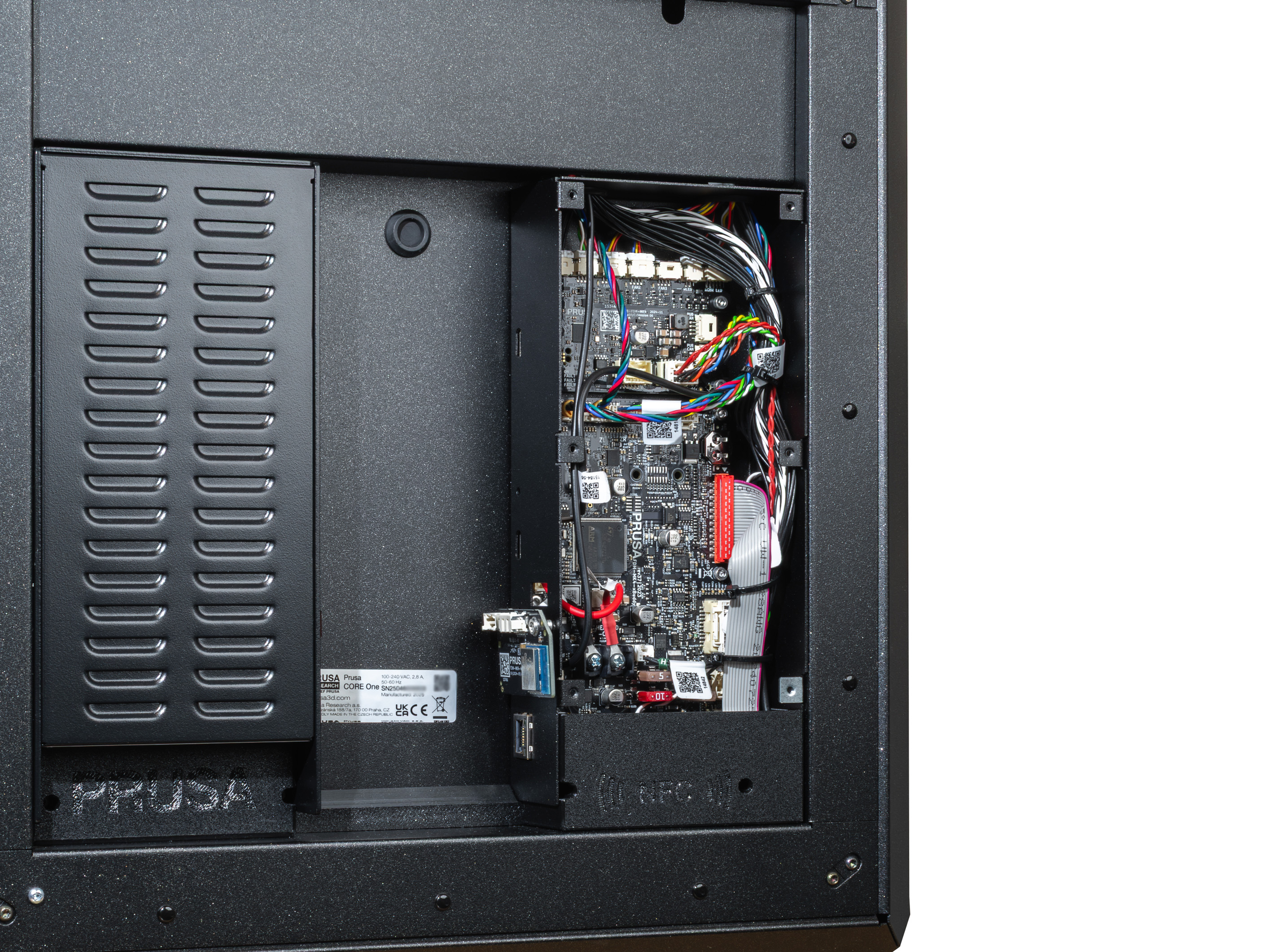
- Cierra la tapa de la caja xBuddy.
- Asegúrate de que el GPIO no toque ninguna parte metálica de la caja xBuddy ni de su tapa.
- ¡Disfruta de tu proyecto!
Pines
Límites - modo de salida
PIN 0 a 3 -> conmuta máx. 24 V, 500 mA (a tierra)
PIN 4 a 7 -> conmuta 0 V o máx. 3,3 V, 10 mA
Límites - modo de entrada
PIN 4 a 7 -> 0 V o 3,3 V (corriente máxima de cortocircuito: 0,5 mA con una resistencia < 4 kΩ).
Descripción
La placa dispone de 8 pines, numerados del 0 al 7. Los pines 0-3 pueden utilizarse como salida, y los pines 4-7 pueden funcionar como entrada o salida. Cada pin es del tipo "open-drain" cuando se utiliza como salida, lo que significa que está controlado por un transistor que conecta el pin a tierra (0 V) cuando está activo. Cuando el pin está inactivo, permanece "flotando", lo que significa que no está conectado a ninguna tensión específica, pero debido a las resistencias pull-up internas, la tensión en el pin puede rondar los 3,3 V.
El comportamiento de los pines en estado de drenaje "open-drain" cuando se utilizan como salidas puede explicarse del siguiente modo:
- Pin configurado como 0 (LOW): El pin está apagado y se encuentra en estado "flotante", lo que significa que no está conectado a ninguna tensión específica. En este estado, la tensión del pin puede fluctuar y no está bien definida a menos que se estabilice mediante una resistencia de pull-up.
Este estado "flotante" puede hacer que la patilla capte ruidos eléctricos aleatorios o interferencias, provocando un comportamiento no deseado si no se gestiona adecuadamente.
- Pin configurado como 1 (HIGH): El pin está encendido y conectado a tierra (0 V), lo que provoca que la tensión en el pin caiga a 0 V. Este estado es claro y no provoca ninguna ambigüedad en la detección de la señal.
Cuando los pines se utilizan como entradas, pueden detectar el nivel de tensión que se les aplica. El estado de la entrada se ve influido por la presencia de resistencias de pull-up, que pueden ayudar a garantizar una tensión alta constante (3.3 V) cuando no se aplica ninguna otra fuente de tensión.
Resistencias pull-up
La placa permite la conexión de resistencias pull-up externas mediante puentes de soldadura etiquetados como JP4 a JP7. Estos puentes están situados en el centro de la placa y se conectan a los pines correspondientes.:
- JP4 está conectada al Pin 4
- JP5 está conectada al Pin 5
- JP6 está conectada al Pin 6
- JP7 está conectada al Pin 7
Los puentes JP7 a JP4 se pueden utilizar para conectar resistencias de pull-up integradas, lo que garantiza que los pines permanezcan a un voltaje alto (3.3 V) cuando no son activamente bajados por una fuente externa o por el estado de salida del pin. Estas resistencias pull-up tienen un valor de 10K ohmios, que es un valor estándar para proporcionar una tensión estable sin consumo excesivo de corriente.
Si no se suelda el puente, la patilla puede permanecer en estado flotante, lo que podría provocar un comportamiento inestable. JP significa "jumper": si el jumper no está soldado, la resistencia estabilizadora de 10 kOhms no está conectada a la puerta y su señal.
Para los usuarios menos experimentados, es importante entender que las salidas "open-drain" no producen intrínsecamente un alto voltaje (3.3 V), sino que permiten una conexión a tierra (0 V). Las resistencias de pull-up son necesarias para asegurar que el pin permanece a un alto voltaje cuando está apagado o cuando se utiliza como entrada. Si no se gestiona adecuadamente, una tensión «flotante» puede hacer que la patilla capte ruido eléctrico, provocando conmutaciones no deseadas o inestabilidad del sistema.
Comprendiendo los valores de los pines
Para utilizar registros avanzados o leer varios pines a la vez, la placa utiliza un sistema binario-decimal. Cada pin tiene un "peso" numérico único. Para seleccionar varios pines, suma sus pesos.
| Pin | 0 | 1 | 2 | 3 | 4 | 5 | 6 | 7 |
| Weight | 1 | 2 | 4 | 8 | 16 | 32 | 64 | 128 |
- Ejemplo: si deseas utilizar el pin 0 y el pin 1, el valor es 1 + 2 = 3.
- Ejemplo: para configurar todos los pines (0-7) a la vez, el valor es 255.
Configuración del GPIO mediante código G personalizado
Información general
La siguiente es una secuencia de comandos de código G personalizados utilizados para controlar la placa GPIO. Esto te permite configurar los estados de salida, leer los estados de entrada y gestionar otros ajustes avanzados de la placa mediante instrucciones de código G, integrándolos perfectamente con el flujo de trabajo de su impresora 3D.
Control de pines mediante código G
Para controlar los pines de salida de la placa GPIO, puede utilizar los siguientes comandos G-Code:
- Configurar el Modo de los Pines (Salida o Entrada)
- P<0-7>: Selecciona el número de pin que deseas configurar (de 0 a 7).
- B<0 or 1>: Establecer el modo del pin.
- 0 - configura el pin como salida.
- 1 - configura el pin como entrada.
- Ejemplo: M262 P0 B0 - Configura el pin 0 como pin de salida.
- Configura el estado en un Pin de Salida
- P<0-7>: Selecciona el número de pin en el que se va a configurar (de 0 a 7).
- B<0 or 1>: Guarda 0 para poner el pin en LOW (0 V) o 1 para ponerlo en HIGH (3.3 V).
- Ejemplo: M264 P0 B1 - Establece el pin de salida 0 en HIGH (1).
- Conmutar el estado del Pin de Salida
- P<0-7>: Seleccione el número de pin que deseas configurar (de 0 a 7).
- Este comando invierte el estado actual del pin seleccionado.
- Ejemplo: M265 P0 - Conmuta el pin 0.
Cuando se utiliza M267, el parámetro R selecciona la "carpeta" y el parámetro B proporciona el mapa de pines:
- Configuración Avanzada del Registro (para Usuarios con Experiencia)
Cuando se utiliza M267, el parámetro R selecciona la "carpeta" y el parámetro B proporciona el mapa de pines:
- R<1-3>: Selecciona el registro que desea configurar:
- 1: Registro de Salida. Establece el voltaje para los pines de salida. 0 = Bajo (0V), 1 = Alto (3.3V).
- 2: Registro de Polaridad. Define la lógica. 0 = Normal, 1 = Invertido. Útil para evitar activaciones "fantasma" en los pines 0-3.
- 3: Registro de configuración. Define la dirección. 0 = Salida, 1 = Entrada. (Por ejemplo, B255 convierte todos los pines en entradas).
- B<0-255>: Establece el valor que se escribirá en el registro seleccionado.
- Ejemplo: M267 R3 B255 - Configura el Registro de Configuración con el valor 255 (todos los pines establecidos como entradas).
Para leer el estado de los pines o establecer configuraciones, utiliza los siguientes comandos códigos G:
- Leer Estado del Pin
- P<0-7>: Seleccione el número de pin del que deseas leer (de 0 a 7).
- El valor devuelto indicará si el pin es HIGH (1) o LOW (0).
- Ejemplo: M263 P6 - Lee el estado del pin 6 (devuelve 32 para HIGH o 0 para LOW).
- Leer todo el Registro de Entradas
- Este comando lee el registro de entrada completo, devolviendo un número en formato "estilo" dado que representa los estados de todos los pines de entrada (de 0 a 7).
- Los estados posibles son:
- 1 - HEX DUMP
- 2 - entero de dos bytes con signo, base 10 (int16)
- 3 - byte sin signo, base 10 (uint8)
- la dirección del dispositivo es siempre 32
- Ejemplo: M261 A32 B1 S3 - lee todo el registro de entrada y lo devuelve como byte sin signo base 10
- Lee el Registro del expander IO (Para Usuarios Experimentados)
- esto lee todo el byte del registro dado de una vez
- R<0-3>:
- 0 - Entrada
- 1 - Salida
- 2 - Polaridad
- 3 - Config
- Ejemplo: M268 R3 - Lee el registro de configuración
Interpretación de los Resultados de Lectura
Cuando lees un registro (M268) o la entrada completa (M261), la impresora devuelve un solo número. Utiliza la tabla de pesos para descodificarlo.
| Pin | 0 | 1 | 2 | 3 | 4 | 5 | 6 | 7 |
| Peso | 1 | 2 | 4 | 8 | 16 | 32 | 64 | 128 |
Ejemplos
- Si M268 R0 devuelve 64, el pin 6 está activo.
- Si devuelve 192, entonces tanto el pin 6 (64) como el pin 7 (128) están activos (64+128=192).
Cómo Configurar el Código G para los Pines de Entrada
Para configurar los pines de entrada para su configuración, cada pin de entrada se asigna automáticamente a un archivo de código G específico ubicado en la unidad USB. Estos archivos deben almacenarse en una carpeta llamada "macros" y seguir una estricta convención de nomenclatura: el nombre del archivo debe tener el formato
donde {pin_number} corresponde al pin GPIO específico que está utilizando. Todas las letras de los nombres de archivo deben estar en minúsculas.
Por ejemplo:
- si utilizas el pin 7, el archivo de código G correspondiente debe llamarse btn_7.gcode y colocarse en la carpeta "macros".
- del mismo modo, para el pin 4, el archivo debe llamarse btn_4.gcode
El sistema admite 8 pines de entrada en la placa GPIO, y cada pin se puede asignar a un único archivo código G de esta manera.
Cuando se activa un archivo de código G a través de su pin de entrada correspondiente, el código G almacenado en ese archivo se inyecta inmediatamente en el proceso en curso. Tenga en cuenta que existe un límite de tamaño para cada archivo de código G, que no debe superar los 1024 bytes.
Aunque la convención de nomenclatura (btn_x.gcode) es fija, el contenido del archivo solo está limitado por el firmware de Prusa.
Puede inyectar cualquier código G válido. Esto incluye M600 (cambio de filamento), M112 (parada de emergencia), M104 (cambios de temperatura) o G28 (retorno al origen).
Limitaciones: Las macros se inyectan en el flujo de comandos actual. El sistema no admite actualmente activadores basados en software (por ejemplo, "ejecutar macro cuando finalice la impresión"); los activadores son estrictamente físicos a través de los pines de entrada.
Control de Entrada Avanzado y Activación de Macros
Cuando un pin de entrada se configura mediante M262 y se pone a 1 (modo de entrada), el estado del pin se comprueba periódicamente cada 0,5 segundos.
Si se pulsa un botón conectado al pin (el estado del pin pasa a LOW), se activa un botón de macro. Por ejemplo, un botón en el pin 7 puede ejecutar automáticamente una macro almacenada en el archivo macros/btn_7.gcode en una unidad USB. La macro se inyecta en la secuencia de impresión, con un límite de tamaño de 1024 bytes.
Memoria Persistente
La configuración de los pines y sus estados se almacenan en EEPROM, lo que garantiza que los ajustes de los pines (modos de salida/entrada, polaridad y estados) se conserven incluso después de un ciclo de alimentación.
Los cambios realizados a través de M262, M264, M267 o cualquier otro código G relevante actualizarán la EEPROM, por lo que los ajustes son persistentes.
Casos Extremos
Para los pines 0-3, que carecen de resistencias pull-up internas, configurarlos como entrada sin circuitería externa adicional puede resultar en un estado lógico invertido. Esto puede desencadenar inadvertidamente la ejecución de macros debido a que su estado de reposo por defecto es LOW (0).
Puedes invertir la lógica de los pines de entrada utilizando el Registro de Polaridad (M267 R2 B<valor>). Esta característica es particularmente útil para los pines que no tienen resistencias pull-up (pines 0-3), que por defecto a un estado de reposo de 0 (LOW) y podría desencadenar acciones no deseadas cuando se deja sin configurar.
La principal diferencia en el comportamiento entre los pines proviene del hecho de que los pines 4-7 pueden utilizar resistencias pull-up internas, que los mantienen en un estado HIGH (3.3 V) cuando no se conducen activamente a LOW. Sin embargo, estas resistencias pull-up sólo están activas si los puentes de soldadura correspondientes (JP4 a JP7) están conectados. Si estos puentes no están soldados, los pines 4-7 se comportan de forma similar a los pines 0-3, pasando por defecto a un estado flotante.
Cuando se utilizan pines de entrada para activar macros, el sistema está diseñado para detectar un estado LOW como indicador de un botón pulsado. Para los pines sin resistencias pull-up activas, este estado LOW por defecto puede activar macros inadvertidamente a menos que se utilice la inversión de polaridad..
Advertencias y Limitaciones
Al configurar o escribir en los pines, el sistema emite una advertencia a través del puerto serie si se produce un desajuste entre la operación prevista (por ejemplo, al intentar escribir en un pin de entrada). Es esencial configurar correctamente los pines utilizando M262 para evitar tales conflictos.
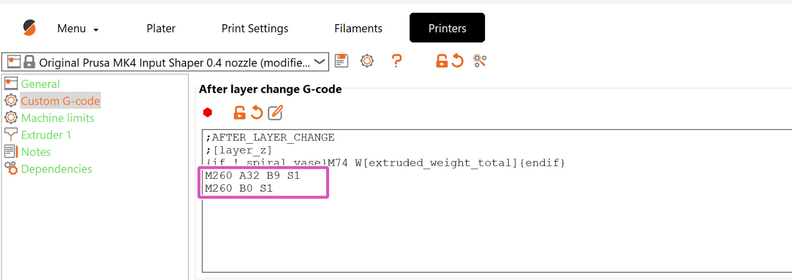
Códigos G personalizados en Prusa Slicer
Inserta el código en los puntos exactos donde se necesita, después/antes de otro comando de código G en particular. En la captura de pantalla de ejemplo, el comando del código G personalizado que controla la placa GPIO se establece a través de PrusaSlicer y se posiciona después de cada cambio de capa. Sin embargo, se puede posicionar en cualquier punto.
Ejemplos
Ejemplo de Conexión del Módulo GPIO al Controlador Externo (filtro de ventilador y LED)
En la imagen adjunta a continuación, podemos ver la conexión entre el módulo GPIO y el controlador externo encargado de controlar el filtro del ventilador y el LED del Original Prusa Enclosure.
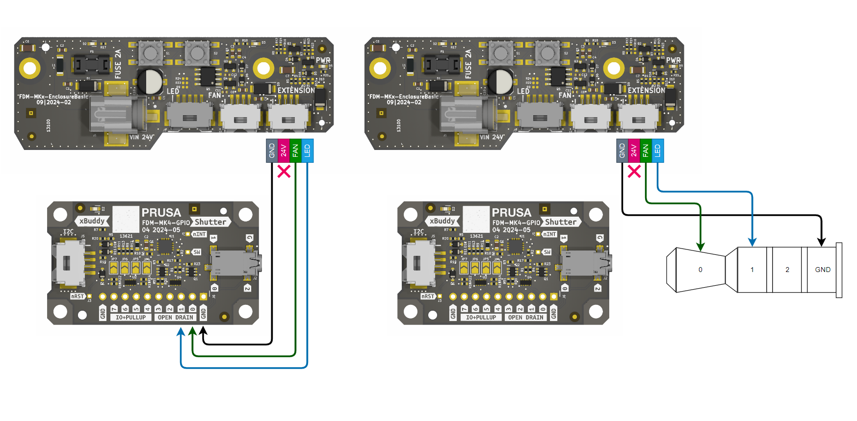
Al conectar la placa GPIO al controlador adicional, la impresora puede automatizar las funciones del cerramiento. Ejemplo:
Dirección: Configura el pin de conexión (por ejemplo, el pin 0) para la salida: M262 P0 B0.
Automatización: En PrusaSlicer, ve a Configuración de la impresora > Código G personalizado.
Código G inicial: Añade M264 P0 B1 para encender las luces/el ventilador del cerramiento cuando comienza la impresión. Código G final: Añade M264 P0 B0 para apagarlos cuando haya terminado.