EN
  • Čeština
  • Español
  • Italiano
  • Deutsch
  • Polski
  • Français
  • 日本語
Login

How to replace PSU on MK3 printers

Menu

How to replace PSU on MK3 printers

How to replace PSU on MK3 printers
Relevant for:
Last updated 5 months ago
How to replace PSU on MK3 printers
 Difficulty
Moderate
 Steps
28
 Available languages
CSPLESDEITFRJA
Introduction
Introduction
This guide will take you through the replacement of the PSU (Power Supply Unit) on the Original Prusa i3 MK3S+, MK3S and MK3.
Follow the instructions and double check your work. There is a risk of damaging the printer, if PSU isn't connected properly!
There are two types of the PSU:
PSU with black casing (PSU holders are on the side of the extrusion)
PSU with silver casing (PSU holders are on the top of the extrusion)
The silver PSU is no longer being produced, in case it needs to be replaced, you will receive the black PSU (new design).
Note that these PSUs are 24V and can't be used on previous generations of Original Prusa i3 printers, which are running at 12 V (e.g. not compatible with MK2.5S, MK2.5, MK2S, ...).
Tools necessary for this chapter
Needle-nose pliers for zip ties.
2.5mm Allen key for M3/M4 screws
3.0 mm Allen key for M5 screws (silver PSU only)
Philips screwdriver for PSU cables
Preparing the printer
Before you start, regardless on the PSU type, make sure that:
the filament is unloaded from the hotend (remove also the spool and the spool holder)
the printer is properly cooled down
the printer is unplugged
Choose your current PSU
This guide includes steps for both PSU types as some printers were already shipped with the new black PSU. Please choose the appropriate sequence of the steps.
On your printer is currently installed:
The black PSU, then please proceed according to the Step 5
The silver PSU, then please proceed according to the Step 13
Disassembly of the black PSU
Release and remove two M3x10 screws. Note that the holes are quite deep.
Remove the printed cover with Prusa logo.
Using a Philips screwdriver release all four screws.
Slide out all the wires.
Unplug the power panic cable (the connector has a safety pin, press it before unplugging)
Removing the PSU from the printer
After you remove all screws, the PSU will fall down, make sure you hold it before releasing the last screw!
Release and remove two M3x10 screws holding the PSU base.
Release and remove the upper M4x10r screw.
Hold the PSU, then release and remove the lower M4x10r screw.
Assembling the new PSU
Take the new PSU and place it above the screws. Adjust the span of the PSU holders.
Slide the PSU on the screws and tighten them, but not too firmly. We need to adjust the position in the next steps.
Make sure you can slide with the PSU up and down.
The screws should be able to hold the PSU in a "vertical" position for now.
Assembling the new PSU
FOLLOW THE INSTRUCTIONS, there is a risk of DEFORMING THE FRAME!
Insert M4 screws in both holes in the frame.
Adjust the position of the PSU, there are holes in the casing, which must align with the holes in the frame. By default the PSU is lower than needed, pull it slightly up.
Tighten the M4 screws but not too firmly, wait for the next instruction.
Before tightening the M4 screws, make sure the PSU is pressed against the printer (aluminium extrusion) and also in direct contact with the vertical frame.
Everything aligned? Tighten the M4 screws.
Now, tighten the M3 screws connecting the PSU with the extrusion.
Connecting the power cables (CRITICAL)
WARNING: Triple-check you have connected the cables correctly!!! There is a risk of damaging the PSU or the printer itself, if the cables are connected incorrectly or not tightened properly!!!
Make sure the bent part of the cable connector is always facing up!!! Use the side with the blue cover. These connectors are slightly wider and won't fit in the Einsy board.
Note that the polarity on the PSU is:
Positive
Positive
Negative
Negative
Keep this in mind while connecting the cables!
Connecting the power cables
Release the screw on the FIRST (positive) slot from the left.
Take the first power cable and choose the RED wire, slide it all the way in. Make sure the steel washer is above the "fork" connector.
Tighten the screw firmly, but keep in mind some parts are made from plastic.
Release the screw on the THIRD (negative) slot from the left.
Take the same cable and choose the BLACK wire, slide it all the way in. Make sure the steel washer is above the "fork" connector.
Tighten the screw firmly, but keep in mind some parts are made from plastic.
Check the connection again! Red wire is in the first slot and black in the third.
Connecting the power cables
Release the screw on the SECOND (positive) slot from the left.
Take the second cable and choose the RED wire, slide it all the way in. Make sure the steel washer is above the "fork" connector.
Tighten the screw firmly, but keep in mind some parts are made from plastic.
Release the screw on the FOURTH (negative) slot from the left.
Take the same cable and choose the BLACK wire, slide it all the way in. Make sure the steel washer is above the "fork" connector.
Tighten the screw firmly, but keep in mind some parts are made from plastic.
Check the connection again! Red wire is in the second slot and black in the fourth.
Power panic and PSU cover
Take the Power panic cable and connect it to the PSU. Both ends of the cable are the same, use any.
Gently bend the Power panic cable and place it close to the power cables. Be careful as you might snap the entire connector from the board, keep that in mind until the printer is fully assembled, don't pull the cable.
Slide the cover on the cables from the top. Make sure the "PRUSA" logo is facing up.
Secure the cover using two M3x10 screws. Note that the holes are quite deep.
It is done! Turn the printer on its feet and turn it on.
The remaining steps of this guide are dedicated to the old silver PSU version.
Disassembly of the silver PSU
Following steps are valid only for the Silver PSU.
Place the printer on the PSU side and cut all of the zip ties holding the cables.
Turn the printer back on its rubber feet and release the M3x40 screw, so you can open the case with the electronics.
Unplugging the PSU cables
Open the Einsy case and unplug following cables:
Four PSU power cables (start from the left, use Philips screwdriver), leave last two heatbed cables connected.
One PSU power panic cable (the connector has a safety pin, press it before unplugging)
Removing the PSU from the printer
After you remove all screws, the PSU will fall down, make sure you hold it before releasing the last screw!
Release and remove two M3x10 screws holding the PSU base.
Release and remove the upper M4x10r screw.
Hold the PSU, then release and remove the lower M4x10r screw.
Lay the PSU down and start pulling the cables out. Proceed carefully and if necessary lift the printer up.
No need to further disassemble the silver PSU, you have all the parts in the replacement package. Keep only the screws holding the PSU.
Rotating the aluminium extrusion
ATTENTION: proceed very carefully during this step. Use reasonable force and don't rotate the printer. We need to adjust part of the frame, which might affect the overall geometry.
The new black PSU has mounting points in a different place, we need to rotate the short extrusion by 90 °.
Start by releasing and removing M5 screws on both sides of this extrusion. Together you need to remove 8 screws. Note that four screws aren't visible in the picture (green arrows).
Carefully and gently rotate the extrusion 90 ° counter-clockwise. Point is to have the silver PSU-holders on the side (facing to the left). AVOID removing the extrusion!!!
Check the silver PSU holders are now on the side (facing to the left).
Insert all eight screws back (from both sides), but first screw them in just slightly, stop about 1 mm from the surface.
Remove the rubber foot by turning and pulling from the side and place it from the bottom, like the rest.
Now, start tightening all the screws. ALWAYS tighten on a diagonal!
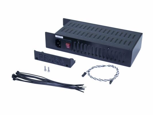
Preparing the PSU replacement kit
For the following steps, please prepare:
24V power supply (1x)
Power panic cable (1x)
M3x10 screw (2x)
PSU-cover-Delta (1x)
Zip tie (10x)
Power cable (2x)
Note there is a bundle of zip ties in the package. You won't use all of them, we are sending a few extra as a spare.
Assembling the new PSU
Turn the back of the printer towards you and locate the PSU holders. Insert M3x10 screws into them. Make only 3-4 turns, it should be enough to hold the PSU for now.
Take the PSU and place it above the screws. Adjust the span of the PSU holders.
Slide the PSU on the screws and tighten them, but not too firmly. We need to adjust the position in the next steps.
Make sure you can slide with the PSU up and down.
The screws should be able to hold the PSU in a "vertical" position for now.
Assembling the new PSU
FOLLOW THE INSTRUCTIONS, there is a risk of DEFORMING THE FRAME!
Insert M4 screws in both holes in the frame.
Adjust the position of the PSU, there are holes in the casing, which must align with the holes in the frame. By default the PSU is lower than needed, pull it slightly up.
Tighten the M4 screws but not too firmly, wait for the next instruction.
Before tightening the M4 screws, make sure the PSU is pressed against the printer (aluminium extrusion) and also in direct contact with the vertical frame.
Everything aligned? Tighten the M4 screws.
Now, tighten the M3 screws connecting the PSU with the extrusion.
Connecting the power cables (CRITICAL)
WARNING: Triple-check you have connected the cables correctly!!! There is a risk of damaging the PSU or the printer itself, if the cables are connected incorrectly or not tightened properly!!!
Make sure the bent part of the cable connector is always facing up!!! Use the side with the blue cover. These connectors are slightly wider and won't fit in the Einsy board.
Note that the polarity on the PSU is:
Positive
Positive
Negative
Negative
Keep this in mind while connecting the cables!
Connecting the power cables
Release the screw on the FIRST (positive) slot from the left.
Take the first power cable and choose the RED wire, slide it all the way in. Make sure the steel washer is above the "fork" connector.
Tighten the screw firmly, but keep in mind some parts are made from plastic.
Release the screw on the THIRD (negative) slot from the left.
Take the same cable and choose the BLACK wire, slide it all the way in. Make sure the steel washer is above the "fork" connector.
Tighten the screw firmly, but keep in mind some parts are made from plastic.
Check the connection again! Red wire is in the first slot and black in the third.
Connecting the power cables
Release the screw on the SECOND (positive) slot from the left.
Take the second cable and choose the RED wire, slide it all the way in. Make sure the steel washer is above the "fork" connector.
Tighten the screw firmly, but keep in mind some parts are made from plastic.
Release the screw on the FOURTH (negative) slot from the left.
Take the same cable and choose the BLACK wire, slide it all the way in. Make sure the steel washer is above the "fork" connector.
Tighten the screw firmly, but keep in mind some parts are made from plastic.
Check the connection again! Red wire is in the second slot and black in the fourth.
Power panic and PSU cover
Take the Power panic cable and connect it to the PSU. Both ends of the cable are the same, use any.
Gently bend the Power panic cable and place it close to the power cables. Be careful as you might snap the entire connector from the board, keep that in mind until the printer is fully assembled, don't pull the cable.
Slide the cover on the cables from the top. Make sure the "PRUSA" logo is facing up.
Secure the cover using two M3x10 screws. Note that the holes are quite deep.
Guide the cables to the other side of the printer. We will fix them to the frame in the next step.
Cable management
Cable management
Cable management
Guide the power cables and power panic cable along the frame and fix it using zip ties.
Here is an example, how to insert and tighten the zip tie:
Using a zip tie create a loop.
Insert power cables and power panic cable to the bundle.
Push the cable gently in the zip tie and tighten it so it is snug and holding the wires. Be careful not to over tighten the tie as it can cut the wires . Cut the remaining part.
Detailed cable management is available in the MK3S assembly: MK3S Cable management
Cable management
Cable management
Cable management
Guide all the cables towards the case with electronics.
Push the cables gently in the zip tie, before you tighten the zip tie, read the next point.
Be very careful! Tighten the zip tie slightly or you will damage the LCD cables! The zip tie should be snug to hold the wires in place. Over tightening it can cut the wires!
That's it! Cables are organised, let's connect them to the EINSY board. Now you can turn the printer back on its feet.
Detailed cable management is available in the MK3 assembly: MK3 Cable management
PSU power cables
PSU power cables
PSU power cables
IMPORTANT: it is CRUCIAL to connect the PSU cables in correct order to the EINSY board. POSITIVE WIRE must be connected to POSITIVE SLOT. There are TWO VERSIONS of the cables with different colouring system:
Version A: both wires on each pair are black, POSITIVE WIRE is marked with a RED LINE
Version B: on each pair, there is a red and black wire. POSITIVE WIRE is FULLY RED.
Connect wires from PSU to the EINSY board in the following order (red arrows indicate positive slot):
The first cable from the PSU (A+|A-).
The second cable from the PSU (B+|B-).
Check also the heatbed cables (C+|C-), make sure the screws are properly tightened ;)
Both cables (two pairs) from the PSU are the same, their order doesn't matter, just ensure correct polarity.
Power panic cable
Power panic cable
Last step is to plug in the power panic cable. Since there is a safety pin on the connector, there is only one correct orientation.
Final check
Final check
Final check
Before you close the box, triple check your cables! Have you used the proper polarity? Are all the cables properly tightened?
All checked? OK, close the door, take the M3x40 screw and tighten it.
Plug the printer in and turn it on.
Since we were rocking with the printer, run Z-axis calibration from the menu.
In case of issues with the print quality, check the frame geometry and rerun XYZ calibration.
Our work is done here! Good job ;)
Was this guide helpful?

Comments

Still have questions?

Still have questions?

If you have a question about something that isn't covered here, check out our additional resources.
And if that doesn't do the trick, you can send an inquiry to [email protected] or through the button below.

Contact us