EN
  • Čeština
  • Español
  • Italiano
  • Deutsch
  • Polski
  • Français
Login

2. YZ - axis assembly

Menu

2. YZ - axis assembly

2. YZ - axis assembly
Relevant for:
Last updated 8 months ago
2. YZ - axis assembly
 Difficulty
Moderate
 Steps
63
 Available languages
CSPLDEESITFR
Y-carriage: parts preparation
All the printed parts and fasteners needed for this chapter are included in the box: YZ & X-axis
For the following steps, please prepare:
Y-carriage (1x)
M3nN nyloc nut (6x)
M3x10r screw (6x)
Bearing clip (3x)
Linear bearing LM8UU (3x) included in the Rods package
The list continues in the next step...
Y-carriage: parts preparation (lubricating)
For the following steps, please prepare:
Prusa lubricant applicator (1x)
Prusa lubricant (1x)
Several paper towels to wipe oil and grease from the bearing surface.
Each bearing must be lubricated before mounting on the printer. Follow these instructions carefully.
Lubricating the bearing
Use any piece of fabric as a pad to protect your working surface from grease.
Make sure the bearing is clean inside.
Wipe the preservative oil off the bearing surface with a paper towel.
It is necessary to lubricate all 4 rows of balls inside the bearing.
Open the lubricant and pierce the hole in the tube with the tip in the cap.
Screw the tube into the applicator.
Carefully slide the entire bearing onto the applicator.
Lubricating the bearing
Turn the tube and applicator counterclockwise until you feel a slight resistance. This means that the holes in the applicator are aligned with the ball rows.
Gently press the tube to push the lubricant into the ball rows of the bearing.
Look at the front of the bearing. When the applicator pushes the lubricant out (around the black gasket), stop pressing the tube. Hold the bearing with the other hand during the lubricating.
The grease must be spread evenly over all four ball rows inside the bearing. There must not be too much grease, or too little. Take a closer look at the last picture.
Wipe off excess grease on the outside of the bearing with a paper towel.
Use this procedure for all three bearings.
Do not remove the applicator from the tube. Keep it prepared for the next chapter.
The bearings may leave excess grease on the smooth rods after their installation. Wipe off any residue with a paper towel.
Correct bearing orientation
The correct orientation: When placing bearings onto the Y-carriage, make sure that they are oriented as shown in both pictures. The tracks (rows of balls) have to be on the sides.
The incorrect orientation: Avoid placing the bearing like in the last picture! This orientation with a single row of balls in the center of the hole will later increase the wear of the smooth rod, possibly creating a groove in it.
Installing bearings on the Y-carriage
Insert linear bearing in the center of the cutout. It doesn't matter which side. The top side and bottom side are the same.
Place the bearing clip over the bearing.
Insert two M3x10r screws into the holes in the bearing clip.
Using your fingers, hold the heads of both screws and turn the Y-carriage. Place the nyloc nuts on both screws.
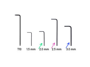
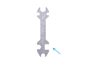
Tighten both nuts by using the 2 mm Allen key and the universal wrench.
Repeat these steps for the remaining two linear bearings.
Installing the heatbed spacers
Insert the M3x8 screw from the bottom of the Y-carriage (the side with bearings).
Screw the heatbed spacer onto the screw from the top side of the Y-carriage and tighten it with the universal wrench and 2.5mm Allen key. Tighten it firmly, but gently!
Use this procedure for all 9 heatbed spacers.
Place the MINI-Y-belt-holder on the bottom side of the Y-carriage.
Orient the holder so that the side with the teeth faces the side with one bearing!!!
Double-check the MINI-Y-belt holder orientation!!!
Secure it with two M3x12 screws. There is no need of a nut on the opposite side. There are threads in the Y-carriage.
Comparison of extrusions
Take all the extrusions and compare their lengths.
You will need two shorter (262 mm) extrusions for the Y-axis assembly.
Mounting the Y-plate-front
Place the short extrusion to the left "inner" side of the MINI-Y-plate-front. See the protrusion on the plastic part. Do not place the extrusion directly on the protrusion on the left. There must be a gap. See the picture.
Slide the extrusion onto the plastic part so that the protrusion fits in the extrusion.
Secure both parts with two M5x20r screws. When tightening the M5x20r screws, push on the extrusion from above.
Mounting the MINI-Y-plate-front
Place the short extrusion to the right "inner" side of the MINI-Y-plate-front. See the protrusion on the plastic part.
Slide the extrusion onto the plastic part so that the protrusion fits in the extrusion.
Secure both parts with two M5x20r screws. When tightening the M5x20r screws, push on the extrusion from above.
Preparing MINI-Y-belt-idler
Take the MINI-Y-belt-idler and insert the M3nS nut from one side.
Turn the idler 180° and insert the M3nS nut from the other side.
Insert the M3nN nut into the hexagonal hole on the side. Push the nut as far down as possible.
Always make sure that all M3nS nuts are inserted all the way down into the holes.
Preparing MINI-Y-belt-idler
Insert the pulley in the MINI-Y-belt-idler. The orientation of the pulley doesn't matter.
Secure the bearing with the M3x20 screw. Don't fully tighten the screw.
Place your finger on the bearing and ensure it can rotate freely. If needed, adjust the screw.
Mounting the MINI-Y-belt-idler
Place the MINI-Y-belt-idler on the MINI-Y-plate-front. See the orientation of the part according to the picture.
Secure the MINI-Y-belt-idler with two M3x20 screws.
Do not tighten the screws at this time. Leave a gap of 1-2 mm between the MINI-Y-belt-idler and the MINI-Y-plate-front.
Y-axis smooth rods: parts preparation
For the following steps, please prepare:
Smooth rods (2x)
There are two sizes of the smooth rods. Prepare two rods with the smaller diameter (8 mm) now. Smooth rods with a larger diameter (10 mm) will be used later.
M3nE nut (3x)
The latest kit units contain M3nEs nuts. The M3nEs nut is slightly different, it has a sheet metal spring. However, the installation procedure is the same.
Assembling the Y-carriage
NOW, PLEASE BE VERY CAREFUL! Gently insert the rod straight into the bearings. Do not apply too much force and do not tilt the rod!
If you can't slide the smooth rod easily, check to make sure that the two bearings are aligned properly.
In case you manage to push out balls from the bearings, please count them. One or two balls are ok, if there are more of them, please consider ordering new bearings.
The bearings may leave excess grease on the smooth rods after their installation. Wipe off any residue with a paper towel.
Mounting the Y-carriage
Place the Y-carriage on the extrusions. The side with one bearing must face to the left.
Gently slide the smooth rods into the holes in the MINI-Y-plate-front. Start with the left rod, then the right one.
Insert two M3nE into the side groove of the left extrusion (side with one bearing on the Y-carriage).
Insert one M3nE nut into the upper groove of the left extrusion (side with one bearing on the Y-carriage).
Before proceeding to the next step, make sure you have inserted all three M3nE nuts. Later insertion is difficult.
Don't forget to wipe off the residue of the grease on the smooth rods with a paper towel.
Y-axis rear: parts preparation
For the following steps, please prepare:
MINI-Y-plate-rear (1x)
M5x20r screw (4x)
Y-axis motor (1x)
M3x12 screw (3x)
Pulley T16-2GT (1x)
Y-axis motor assembly
There is a flat part on the motor shaft, rotate it similarly to the first picture. See the direction of the arrows.
Place the pulley T16-2GT on the Y-motor shaft as shown in the picture.
Don't press the pulley against the motor. Leave a two-millimeter gap between both parts. Use the universal wrench to set the gap.
One of the screws must be facing directly against the pad (flat part) on the shaft. Slightly tighten the first screw.
Turn the shaft and slightly tighten the second screw.
Ensure you have the correct orientation of the pulley on the shaft. It can be placed both ways, but only one is correct.
Mounting the Y-motor
Place the Y-axis motor to the holder on the MINI-Y-plate-rear part.
Make sure the cable from the motor is oriented in the same way as in the picture.
Secure the Y-axis motor with three M3x12 screws.
Mounting the MINI-Y-rear-plate
Once again, make sure that all three M3nE nuts are placed in the extrusion.
Place the MINI-Y-plate-rear on the smooth rods.
Push the MINI-Y-plate-rear all the way onto both extrusions.
Secure both parts with two M5x20r screws. When tightening the M5x20r screws, push on the extrusion from above.
To prevent damage to the Y-axis motor cable during the assembly, place the cable into the extrusion.
Anti-vibration pads installation
Gently push four pads out of the block.
Keep the other two pads for later.
Peel the protective film from all four pads.
Rotate the Y-axis so that the Y-carriage is facing down and glue four pads on the aluminum extrusions, like in the picture. Pay careful attention to the correct orientation.
It is recommended to place the Y-carriage on a piece of fabric. Heatbed spacers can scratch your workbench.
Do not glue any of these four pads on the plastic front and rear plate!
Y-axis belt guidance
Insert one end of the belt into the lower groove of the MINI-Y-belt-holder. Make sure the belt teeth are facing up.
Guide the belt around the MINI-Y-belt-idler pulley.
Guide the belt around the Y-axis motor pulley.
Insert the second end of the belt into the upper groove of the MINI-Y-belt-holder.
Secure both ends of the belts by squeezing them into the groove with the 1.5mm Allen key.
Aligning the Y-axis belt
Make sure the belt is placed in the "axis" of the printer. Both top and bottom part of the belt should be parallel (above each other).
To adjust the belt position, release screws on the pulley, and with slight movements, proceed until you reach the best position.
Tighten both screws on the pulley.
If the belt doesn't line up, check that the pulley is in the same orientation as seen in the picture.
Y-belt tensioning
Y-belt tensioning
Y-belt tensioning
Move the Y-carriage all the way from you.
Using a finger on your left hand push the belt down. Some force should be needed for bending the belt, BUT don't try to overstretch the belt as you might damage the printer.
You can change the tension in the belt by adjusting the two screws on the MINI-Y-plate-front:
Tighten the screw, bring the MINI-Y-belt-idler closer and thus increase the overall tension.
Release the screw, parts will move apart, the overall tension will decrease.
Use the technique described below to test if the belt is properly stretched.
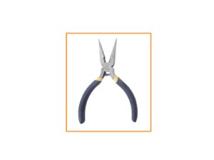
Use pliers to hold the Y-axis motor shaft.
Move the Y-carriage with your hand towards the Y-axis motor. Don't use excessive force.
If the belt is stretched properly, you should feel a resistance and the Y-carriage won't move at all. If the belt is too loose, it will deform (create a "wave") and jump over the teeth on the pulley.
Belt tension check
Belt tension check
This step is recommended, but optional. If you don't have a phone at your disposal, continue to the next step. You can do this check later on.
To verify or fine-tune the X or Y-axis belt tension on your printer, visit prusa.io/belt-tuner and open up the webpage on your mobile device. Or using your phone, scan the QR code in the picture.
Follow the on-screen instructions to fine-tune the belt tension.
The belt tuner app was tested on multiple phones and should work across all most common phone manufacturers. However, in some rare cases it might not work as expected. Please state your brand and model in the comments below the step.
Y-axis assembly: reward yourself!
You just finished the Y-axis assembly. It wasn't that hard, was it? Now is the time to reward yourself and replenish your energy for the next steps. Please, follow these instructions:
Carefully and quietly open the bag with the Haribo sweets. High level of noise might attract nearby predators!
Each row of the bears is intended for a specific chapter or is split into specific parts of the chapter. The number of the bears is sorted according to the difficulty of the chapter. But don't worry ;).
Spread the bears in the six rows according to the picture. Start from the top.
If you are missing some bears, do not hesitate and immediately visit the nearest candy store and buy the missing amount ;).
Keep the correct number of the bears in separate rows. That is crucial!
Eat the first part of the first row.
MINI-Z-bottom: parts preparation
For the following steps, please prepare:
Fasteners needed for the following steps are in the Y & Z-axis package. Please, prepare this bag.
MINI-Z-bottom (1x)
M3n nut (4x)
M3nS nut (8x)
Anti-vibration foam pad (1x)
The remaining foam pad is a spare.
Assembling the MINI-Z-bottom
Look inside the MINI-Z-bottom, locate two holes and insert two M3nS nuts. Use the 1.5mm Allen key to push the nuts fully inside.
Insert one M3nS nut into the hole on the side.
Insert one M3nS nut from the front side of the part.
Always make sure that all M3nS nuts are inserted all the way down into the holes.
Assembling the MINI-Z-bottom
Insert two M3nS nuts from the top side of the MINI-z-bottom.
Turn the part upside down and insert two M3nS nuts.
Insert four M3n nuts. Make sure they are flush (aligned) with the surface of the printed part. Do not press too much on the bottom of the plastic part, it may crack.
Glue the anti-vibration pad in the recess shape of the pad.
Buddy board: parts preparation
For the following steps, please prepare:
WARNING: Make sure to protect the electronics against electrostatic discharge (ESD). Always unpack the electronics right before you need them!
Buddy board (1x) Keep the silver label for later!
New kit units are shipped with the silver label already affixed to the longest aluminum extrusion.
Note that the anti-static bag will be opened upon arrival. Each board is taken out and tested before shipping.
M3x8 screw (4x)
Mounting the Buddy board
WARNING: Make sure to protect the electronics against electrostatic discharge (ESD). Always unpack the electronics right before you need them!
Grab the Buddy board on the sides and insert the board into the MINI-Z-bottom.
Make sure the LAN and power connectors are properly seated in the holes.
Secure the board with four M3x8 screws. Do not tighten too much! You can crack the Buddy board.
You can insert the screws with the needle-nose pliers. But be careful, avoid scratching the printed circuit board or bend the capacitors. You can fatally damage the Buddy board.
LCD cable: parts preparation
For the following steps, please prepare:
LCD cable (1x)
The LCD cable is not symmetrical. Carefully read the instructions for the correct connection.
Connecting the LCD cable
Take the LCD cable and push it through the hole in the MINI-Z-bottom.
Make sure the "tooth" on the connector is facing up.
Make sure the cable fold in the connector is facing up.
Connect the LCD connector to the board. Mind the orientation of the connector, there is a notch on one side (see the orange circle).
LCD cable guidance
LCD cable guidance
LCD cable guidance
WARNING: From now on proceed carefully while moving the XZ-axis. The LCD cable is facing down and might get damaged.
In order to protect the cable, please follow the instructions below. Also, don't try any other orientation, because it will complicate the assembly.
Wrap the LCD cable around the box. Don't stretch the cable.
Fold the second end of the cable inside the MINI-Z-bottom.
Z-axis: parts preparation
For the following steps, please prepare:
Extrusion 289 mm (1x)
Z plate bottom (1x)
M5x20r screw (2x)
M3x12 screw (2x)
M3x20 screw (3x)
M3x40 screw (1x)
Assembling the Z-axis
Place the Z plate bottom part on the front of the extrusion like in the picture.
Secure it with two M5x20r screws.
If you have the silver label already affixed to the extrusion from us, orient it to the same side, as in the picture.
Assembling the Z-axis
There is a screw head on the underside of the Z plate bottom which must be properly seated in the round groove in the MINI-Z-bottom. Follow these instructions for the correct installation:
Place the extrusion assembly on the MINI-Z-bottom like in the picture and slightly tilt the extrusion. Move the inclined extrusion to the edge of the plastic part (see the yellow circle).
Straighten the extrusion to 90 °.
Assembling the Z-axis
Make sure there is no large gap between the Z plate bottom and the plastic part.
Secure the Z plate bottom with two M3x20 screws.
Insert one M3x12 screw in the Z plate and tighten it.
Insert the M3x40 screw into the hole in the MINI-Z-bottom.
Using the 2.5mm Allen key insert the screw through the entire part so that a tip of the screw is visible on the other side.
Connecting the Y and Z-axis
Move the Y-carriage all the way to the left.
Place the right M3nE nut approximately in the middle of the extrusion length.
Align the Y-axis and Z-axis so that the protruding M3x40 screw points exactly at the hole in the M3nE nut in the extrusion. Join both parts together. DON'T tighten the screw fully yet!
Joining the Y and Z-axis together
Take the second M3nE nut from the left and move it all the way to the right, use the Allen key and gently push it in. There is a notch inside, which will align it properly for the second screw.
Use the M3x20 screw and again tighten it just slightly, but ensure you have reached the nut. DON'T tighten the screw fully yet!
Joining the Y and Z-axis together
Take the M3nE nut in the upper groove of the extrusion and slide it under the steel plate.
Make sure the hole in the nut matches the hole in the plate. Use the Allen key to align it.
Fix both parts together using the M3x12 screw, tighten it slightly. DON'T tighten the screw fully yet!
Aligning the YZ-axis assembly
In this step you will move the entire Z-axis, avoid pushing (grinding) it against the aluminium extrusion, or you might scratch it. Leave a small gap while moving the parts.
Rotate the back of the printer towards you and push the Y-carriage all the way to the "front".
Hold the Y-axis assembly.
Move the Z-axis assembly to the back.
There is a notch, which indicates the correct mutual position of both parts.
Securing the YZ-axis assembly
Once the parts are aligned, tighten all screws in this particular order:
First, the M3x12 screw at the top.
Second, the M3x40 screw on the side.
Third, the M3x20 screw on the side.
Guiding the Y-axis motor cable
Tilt the YZ-axis assembly as shown.
Remove the Y-axis motor cable from the extrusion.
Guide the Y-axis motor cable through the hole in the MINI-Z-bottom. Pushing the connector through the hole is tight, be careful not to damage the connector.
Do not stretch the cable. Leave a small slack.
Y-axis motor cable guidance
Connect the Y-axis motor cable to the third slot from the left. Arrange the cable guiding according to the second picture.
Do not pull on the cable!
Z-top: parts preparation
For the following steps, please prepare:
MINI-Z-top (1x)
Trapezoidal nut (1x)
Z-axis motor (1x)
M3nS nut (2x)
M3x12 screw (2x)
Assembling the MINI-Z-top
Place the Z-axis motor like in the picture. Note the indicated cable direction.
Place the MINI-Z-top on the Z-axis with the longest part on the right.
Secure the MINI-Z-top with two M3x12 screws.
Screw the trapezoidal nut up to 2/3 of the Z-axis motor length. See the proper orientation of the nut.
Double-check the orientation of the parts!
Z-axis smooth rods: parts preparation
For the following steps, please prepare:
Smooth rod Z-axis (2x)
Now use two rods with the larger diameter (10 mm).
M3x20 screw (4x)
M5x16r screw (2x)
Linear bearing LM10LUU (2x) included in the Rods package
LM10LUU bearings do not need lubrication.
Mounting the Z-axis smooth rods
Push both Z-axis smooth rods all the way into the MINI-Z-bottom.
In case you find it difficult to insert the smooth rods, you can slightly loosen the screws on the Z plate bottom and tighten it again after insertion. Don't forget to tighten them after the insertion.
Look at the MINI-Z-bottom from below and make sure that both smooth rods are fully inserted all the way down and touching the bottom.
Some early units may have a narrower version of the inspection holes. In this case, it is recommended to illuminate the holes with a spotlight for better visibility of the smooth rods.
Secure smooth rods with four M3x20 screws.
Installing the Z-axis bearings
Turn the YZ-axis assembly with the rear side facing you.
Carefully put the bearings on the Z-axis rods. And slide them down.
Mounting the MINI-Z-top assembly
Slide the bearings to the upper edge of the smooth rods and hold them by hand.
With the other hand, position the Z-axis motor so that the trapezoidal nut is under the bearings.
Slide the bearings down on the trapezoidal nut.
Position the MINI-z-top on the extrusion and smooth rods. Then push the MINI-Z-top down on the rods.
Do not tilt the motor when fitting! Insert straight, the threaded rod of the motor must fit into the hole in the Z plate bottom.
Check that the plastic part is seated correctly. There must be no gap between the plastic part and the extrusion.
Mounting the MINI-Z-top assembly
Secure the MINI-z-top with two M5x16r screws.
Guide the Z-motor cable down through groove in the MINI-Z-top and extrusion.
Connect the Z-motor cable to the Buddy control board - first connector from the left.
Securing the MINI-Z-top assembly
Place the plastic cover on the groove with the cable. Align it with the top edge of the extrusion.
Insert and tighten M3x20 screws into the MINI-Z-top part from the opposite side of the YZ-axis assembly.
YZ-axis is finished!
Check the final look, compare it to the picture.
Checked everything? Continue with the chapter 3. X-axis & Extruder assembly.
Was this guide helpful?

Comments

Still have questions?

Still have questions?

If you have a question about something that isn't covered here, check out our additional resources.
And if that doesn't do the trick, you can send an inquiry to [email protected] or through the button below.

Contact us