P.I.N.D.A. stands for Prusa INDuction Autoleveling sensor and is a vital component facilitating the calibration of our printers. There are 3 different versions:
- P.I.N.D.A. V1 - used on MK2/S and MINI.
- P.I.N.D.A. V2 - used on MK2.5, MK2.5S, MK3, and MK3S.
- SuperPINDA - Compatible/used with MK2.5/S, MK3/S/+, and MINI+.
The difference between P.I.N.D.A V1 and V2 is that the P.I.N.D.A V2 has an inbuilt thermistor to compensate for the difference in cold and hot measurements. V1 and V2 are not interchangeable. However, SuperPINDA and PINDA V2 are interchangeable but may require a firmware update. The SuperPINDA does not have a thermistor, as its high-quality components and manufacturing remove the need for one.
Testing the P.I.N.D.A./SuperPINDA sensor
Firstly, we need to check if the sensor works at all. For this test, you need a small and thin metal object (spatula, scissors, pliers). Your printer should also be running on the latest firmware version for your printer model.
- Press the knob next to the LCD for 3 sec and turn it to raise the extruder approximately 10 cm above the heatbed. This is to distance it from any metal.
- If you have firmware version 3.5.3 and later (unless you have an MK2/S), go to the LCD Menu -> Support -> Sensor info and see the sensor value ('PINDA:' 1 or 0)
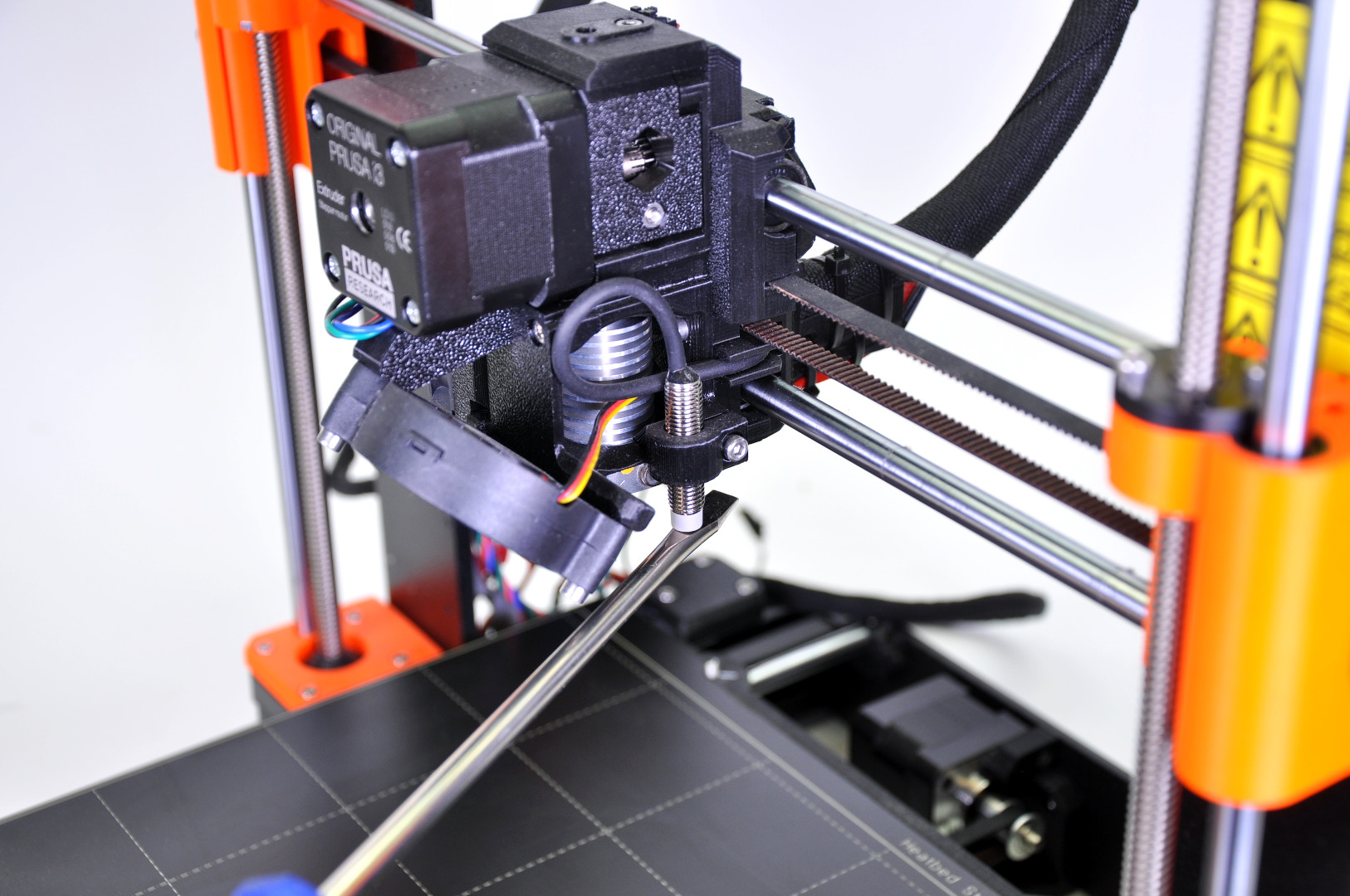
- Place the metal object (spatula, screwdriver, etc.) underneath the P.I.N.D.A./SuperPINDA sensor. The value should change from 0 to 1, and the red light on top of the sensor should turn off.
- Move the extruder by hand all along the X-axis and wiggle with the extruder's cable-bundle. The value should still be 1, as long as there is something metallic under the sensor.
- If the value does not change, make sure the sensor is connected correctly. Please refer to the Einsy RAMBo electronics wiring (MK3/MK3S/MK3S+) or Mini RAMBo electronics wiring (MK2S, MK2.5, MK2.5S) articles.
- If the value is 1 but flicks to 0 at some point, the cable may be broken at some point. Please contact support via email or chat.
Testing the P.I.N.D.A. sensor-readings in Pronterface
There is another way to check whether or not the P.I.N.D.A. sensor works correctly. Please perform the following procedure 3 times. For the sake of consistent measurements, please make sure the tests are done under identical conditions.
Pronterface may not be supported on newer versions of iOS (Apple Laptops) after they dropped the support of 32-bit apps with Catalina. However, there are some workarounds. See this Github thread.
- Connect the printer to your computer following the Pronterface and USB cable guide.
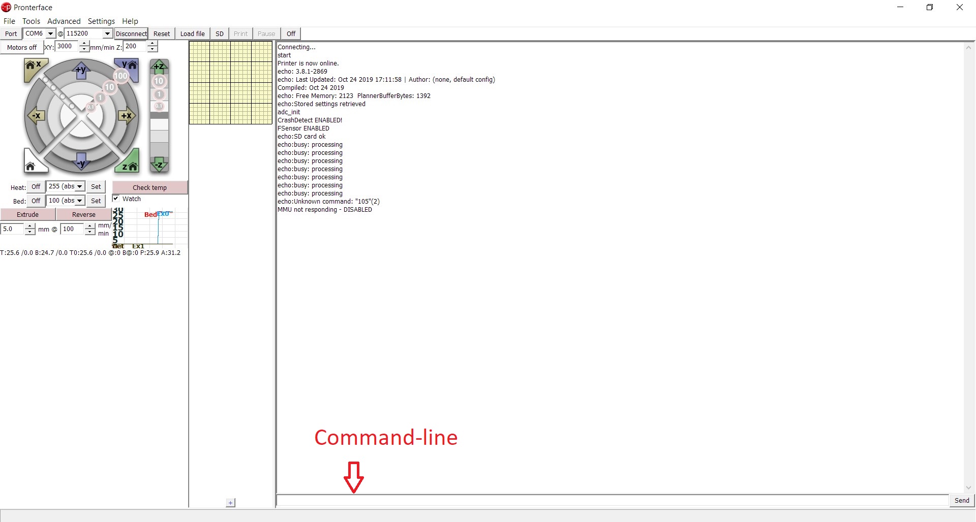
- Issue a G80-command into the command-line. It triggers the mesh bed leveling process.
- Once the process is complete, issue a G81-command which gives you a report of the interpolated Z values for a 7 x 7 array of values.
Compare the data arrays. Keep in mind that every number in the matrix has their pre-defined positions, always compare the numbers in the same position. You want to make sure there are no significant deviations (>0.2) between the 3 measurements.
19 comments
should say:
"newer versions of macOS (Apple Laptops"
I have had a major failure, where the hotend termister wires got so hot they melted and the printer screamed. I couldnt see why and the fuses were not blown.
I have replaced the V6 with the new E3D Revo and the issue looks like its rsesolved. the board powers up and the hotend will heat, extrude, cool, XYZ move and hte PID callibration worked.
BUT the PINDA sensor is no longer working. when i try to do a 1st layer calibration the nozzel hits the bed.
If I follow the instructions above I can see the red light, and I can see if go off when i place a metal object under the PINDA, but the Printer shows a zero the whole time, even when the lights is off.
I have a Mk3 that had the MK3s upgrade. I have flashed the latest 3S firmware and down flashed the previose one incase and it dosnt work. Ive tried the non-s firmware and it has the same behavior.
Question: given that the light is on so the PINDA has power is it more likly that there is a broken cable or that the board is damaged?
Hi! Would the left side work? The right one is being probed by PINDA all the way to the edge.