Modeling for 3D printing presents several interesting challenges. FFF (Fused Filament Fabrication), with its layer-by-layer manufacturing process, the orientation and geometry can greatly affect both the aesthetic and integrity of your finished print. Moreover, different 3D modeling software have different terms and methods for achieving different results, so we will go over some basic guidelines when modeling with 3D printing in mind.
For a complete course on the topic, we offer a 3D Modeling in Autodesk Fusion in our Prusa Academy.
Overhangs and support material
The most important thing to keep in mind while modeling for 3D printing is the need for support material. 3D printers can’t print in mid-air, as each layer has to be laid on top of another one. When designing, keep this limitation in mind and try to avoid creating steep overhangs and extreme angles. That said, short horizontal bridges can be printed without supports.
A 3D printer can cleanly print overhanging structures with an angle between 45 and 60 degrees, depending on your nozzle diameter and settings.
Our FDM printer models with Nextruder and 360° cooling can print overhangs of up to 75° without supports. These models are the MK4S, the CORE One/+, and the CORE One L.
The standard diameter for nozzles on desktop 3D printers is 0.4 mm. For smaller nozzles, like 0.25 mm, the angle might be less than 45 degrees. If you must have very steep overhangs or free-floating geometry in your design, consider if this will be visible in the final product, as surfaces above supports will not have the same finish as a side wall or a top fill. You can model in break-away supports, or split your part into multiple pieces (explained in the next section) for a better orientation.
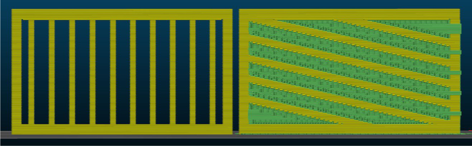
Let’s take a look at an example - you need to design a part of a fence, and it’s up to you how the pickets will look. In the pictures below, you can see two ways to design a fence if we want to print it in a vertical position. The best solution here will be to print the part horizontally.
Splitting the model into multiple parts
Both the visual and mechanical properties of your model can be improved by splitting it into multiple parts. This way, they can be optimized for better orientation and placement on the print platform. This way, you can minimize the number of supports required. The parts of the object can then be glued together. PrusaSlicer has a cut tool to make this easier. You can also use Meshmixer to cut the models.
When you glue the parts of your object together, make sure that the surfaces to be glued are smooth and free of grease or dirt, to achieve an invisible seam. The ironing feature in PrusaSlicer can also assist in this. Also, it can be helpful to lightly sand the surface to increase adhesion. The need for sanding will depend on geometry, surface finish, and the type of glue. Superglue can be very viscous, so it may not be ideal for rough surfaces. It can also leave traces of itself. When you find the right glue for your model and material, the seam should be stronger than the rest of the material, but you might want to model in some pegs for alignment and strength.
Fillet vs chamfer
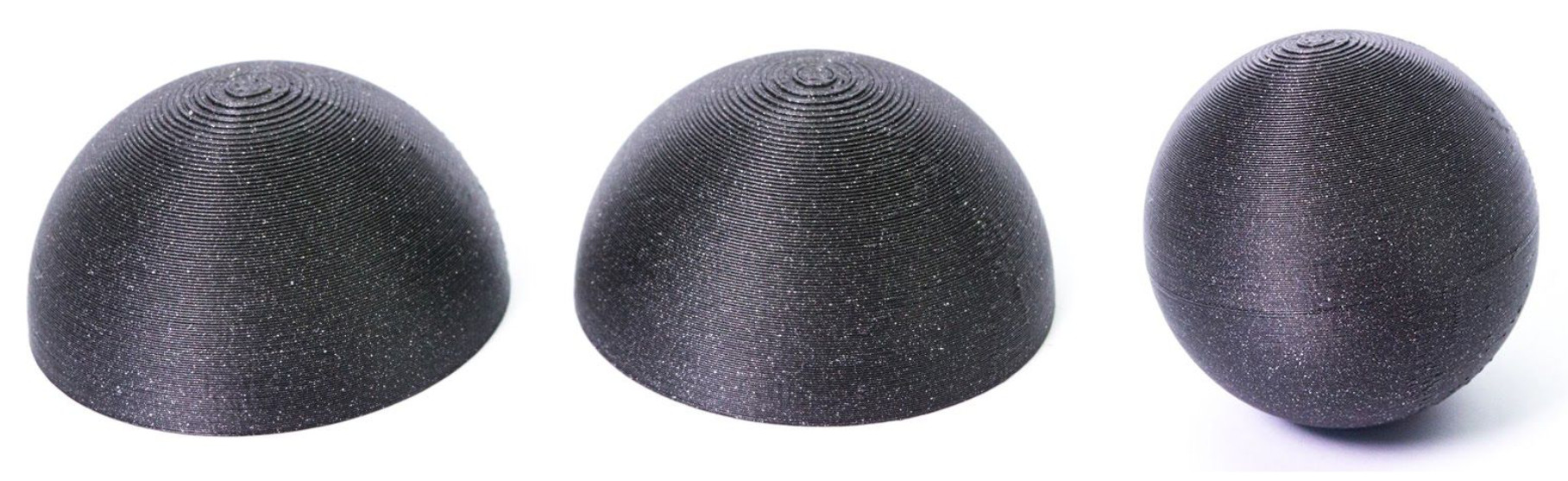
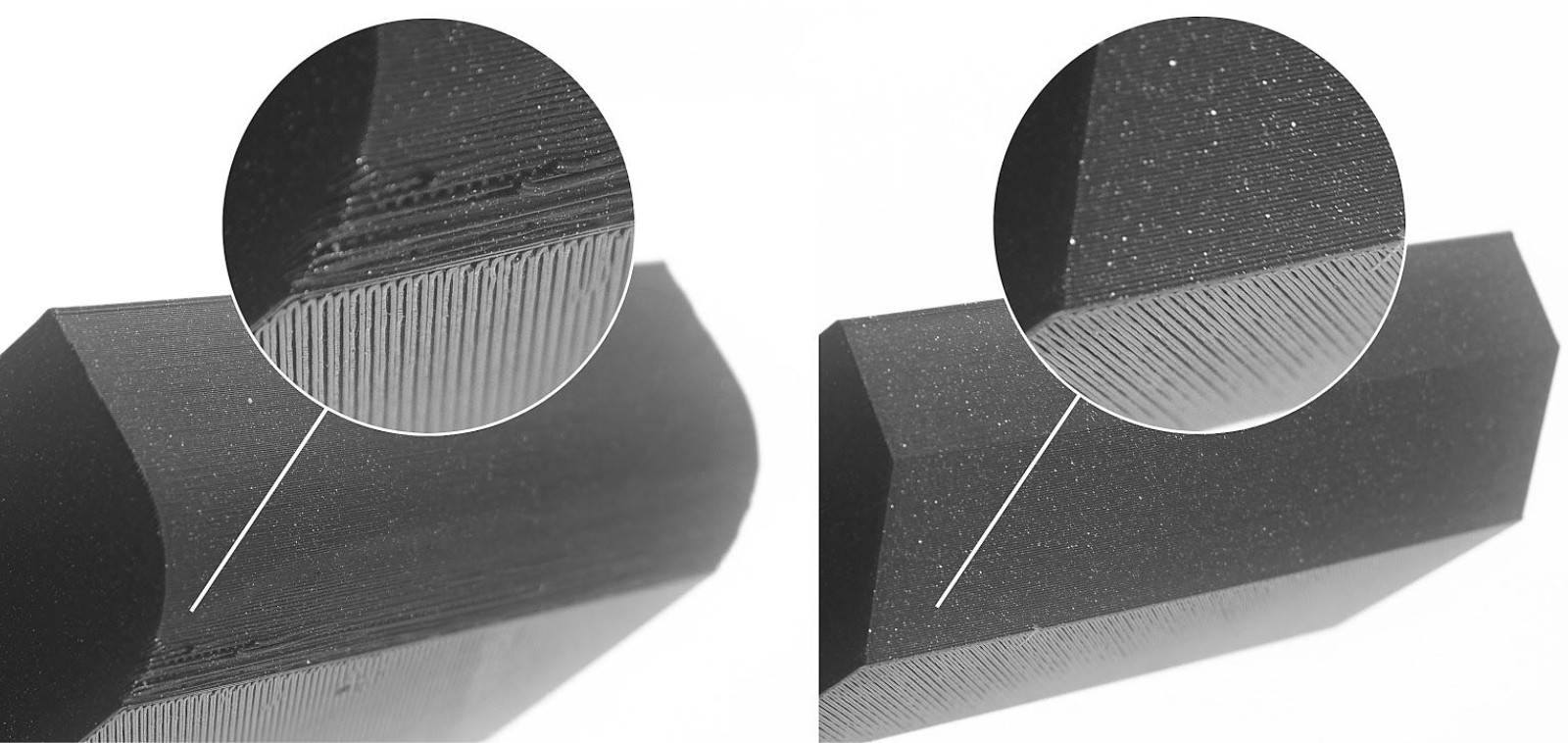
If oriented towards the print bed, fillets create a very steep overhang, which negatively affects the surface of the object. For this reason, use chamfer instead if a perfect part finish is a priority. However, you can improve on this using the Variable layer height function in PrusaSlicer.
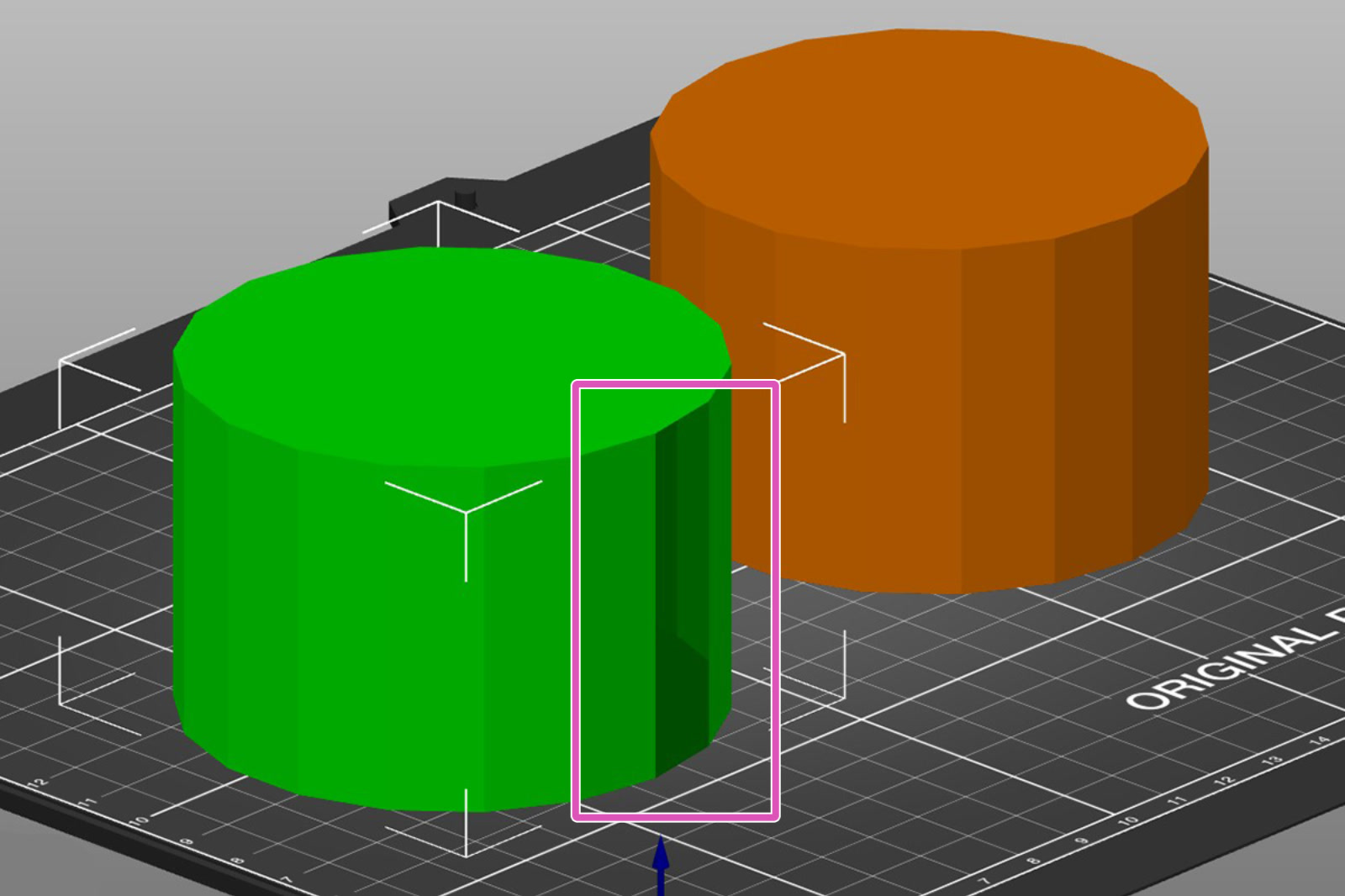
How many sides does your cylinder/circle have?
Bear in mind that the modeling software you are using might be showing you a curve, but pay attention to the number of sides that are actually present. When the model is being designed, the visual representation can be smoothed out by the software's shaders, and the print can turn out to be a polygon, not a circle. Make sure you have the correct number of sides/faces on your model.
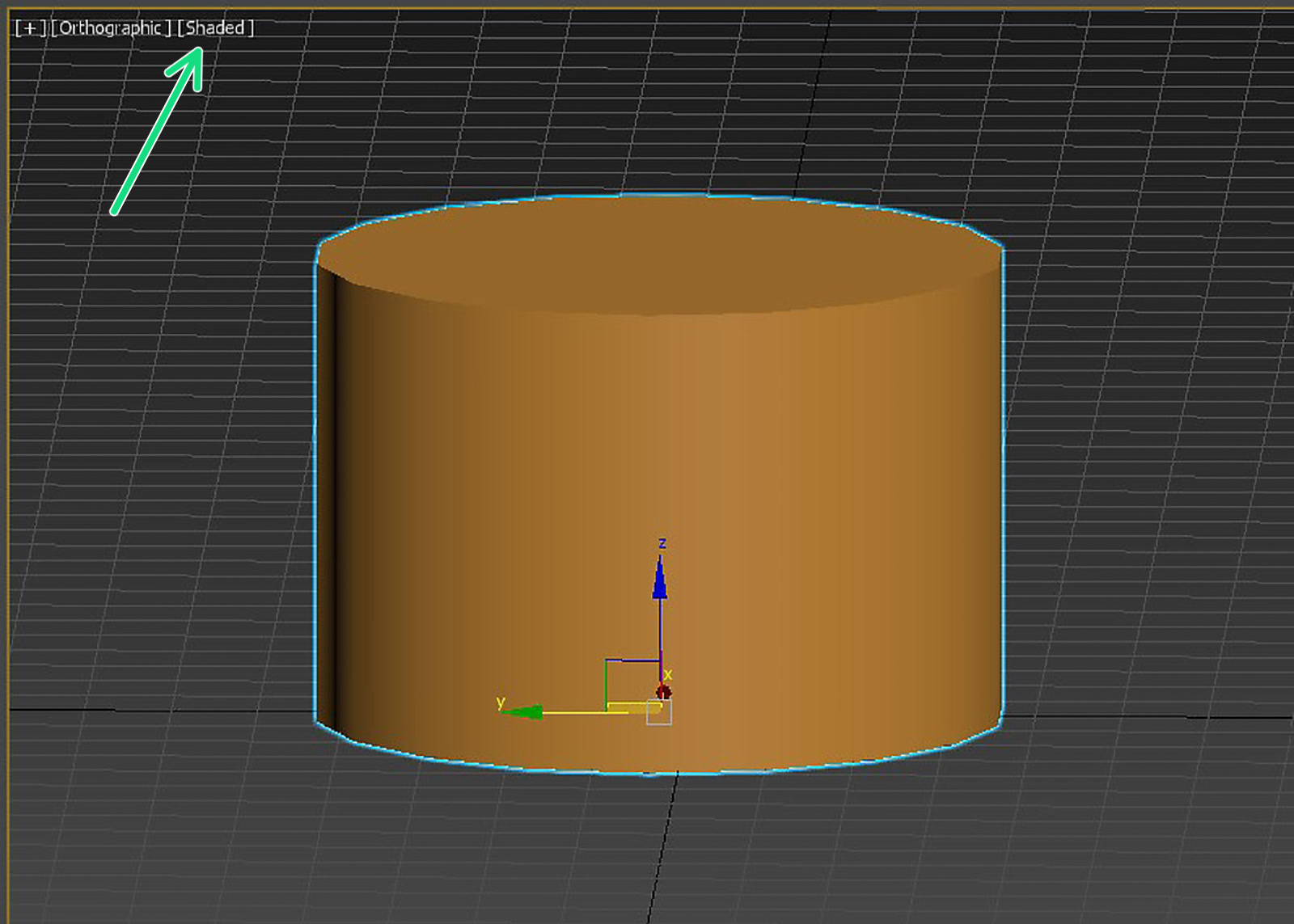 | 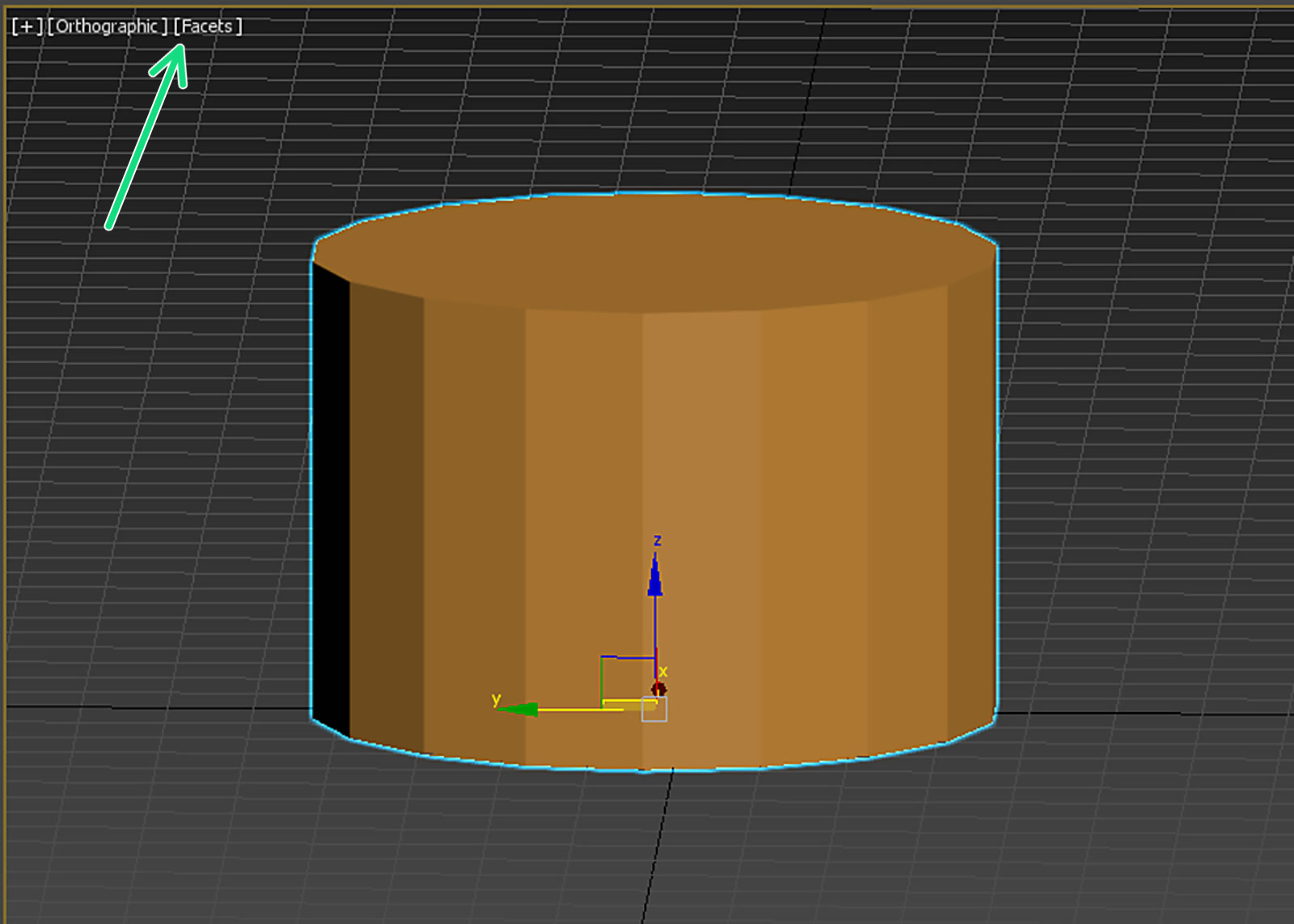 |
Notice how the look of the part changes when changing the shader (green arrow). Both pictures are of the exact same geometry. The right picture shows how it will look printed.
Thin walls and minimum feature size
Another limitation is the nozzle diameter. The most common size and stock nozzle size on MK3S is 0.4 mm, which in PrusaSlicer has an extrusion width of 0.45 mm. PrusaSlicer can improve upon this in multiple ways. However, it may be wise to keep these numbers in mind, especially when you’re designing thin walls or tiny features. Walls thinner than one nozzle perimeter are not printable.
| 0.4 mm nozzle | Wall thickness |
| 1 perimeter | 0.45 mm* |
| 2 perimeters | 0.9 mm* |
| 3 perimeters | 1.35 mm* |
| 4 perimeters | 1.8 mm* |
*These are approximations and may vary depending on the slicer settings.
As a way of improving the perimeters, you can go to the PrusaSlicer to the Print Settings tab - Layers and perimeters, and check the option "Detect thin walls". This will merge two paths into a single-pass extrusion. However, walls thinner than one perimeter can not be "repaired" this way.
| Wall thickness | Is it printable? |
| Less than one perimeter | |
| One perimeter | |
| More than one perimeter, but less than two perimeters | |
| More than two perimeters |
Tolerances
When modeling parts that should fit together, you need to include a certain amount of tolerance. You will probably not be able to slot together two parts with zero-tolerance dimensions. You may have to tweak the tolerances until you reach an optimal result. There’s no single “universal” value - it all depends on different factors, the most common of which are:
- Size of the model
- Horizontal or vertical orientation
- The geometry of the parts that should interlock
- Calibration
- Settings
- Properties of the material
An Original Prusa will be accurate to at least 0.2 mm, but you also need to remember that different materials can warp or shrink during printing. Consider if two parts should move, like a hinge, or lock/snap together with a friction fit. An initial good measurement for movable parts is at least 0.3 mm.
Fine details and material consideration
If you have specific conditions for your design, like being outdoors or in a hot environment, this affects your material choice, which in turn can affect your design decisions. In short, filament properties should be taken into consideration. For example, in order to make designs/models that will need to be outdoors or have high mechanical resistance, those should be printed from PC, ASA, PETG, or similar. Those filaments may not print small details as well as PLA. So when modeling a piece that is meant to endure outdoor weather conditions or mechanical strain, you may want to avoid using small details.
Iterations of your design
You will have to make test prints before you can consider it final. While developing your design, prepare to make tweaks and adjustments to your tolerances and geometry. Having a parametric approach in CAD helps immensely, but if you are just starting out, try not to set your design in stone and save versions along the way, before you, for example, merge multiple objects together and/or create holes/cavities that should fit something else (subtractions).
Orientation on the print bed
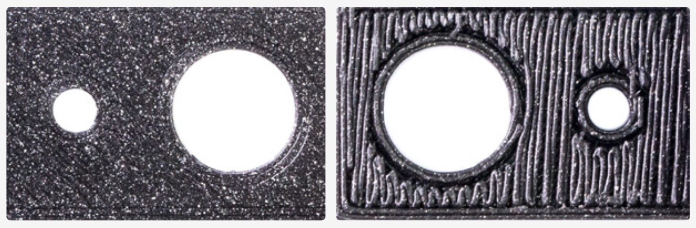
A surface printed directly on the print bed is perfectly flat and smooth, while a surface printed above supports will look more inconsistent and rough. The picture shows the worst-case scenario for demonstration purposes. There are ways to mitigate this, but surfaces with a lower overhang angle look much better even with supports.
Like wood, FFF prints are stronger in one direction than another. Therefore, you want structural parts to be printed in an orientation that optimizes their structural integrity.
Make sure it is manifold/solid
The model to be printed must be solid or have "manifold geometry". This is a geometry that can exist in the 3-dimensional real world. If a model has holes on the surface or internal geometry, the part will not be able to be sliced.
 | 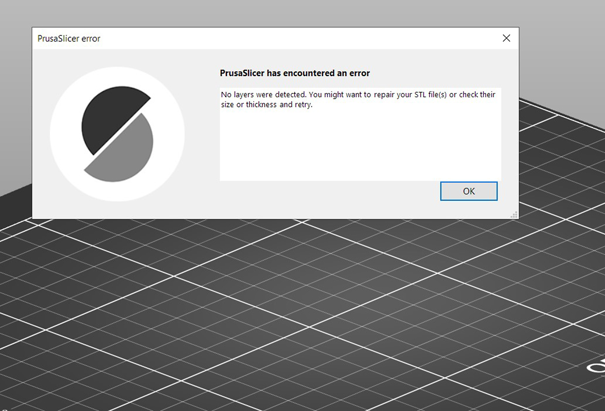 |
Most design programs have a feature dedicated to correcting this error under different terms like "make manifold" or "Cap holes". These options will most often delete excess faces, edges, and vertices, and fix or create surfaces where they are missing. You can also see our guide about Corrupted 3D models for printing.
Multi-material printing and dual extruders
In order for a model to be printed using a printer that supports multi-material printing, such as our MMU3 or our XL in the multi-tool version, several methods for its modeling can be used.
That can be done by having each mesh in a separate 3D file (stl, obj). You can also have multiple meshes in an amf or 3mf file. PrusaSlicer will assign each different mesh to a different color. If you have each mesh in a different file, you will need to import all of them at the same time. We mentioned earlier, making a model manifold or solid. In this case, you will need each part of the whole to be manifold/solid.
It is possible to have one single mesh and split it using Meshmixer, but it can be a very long and tedious process. Therefore, this might be helpful to keep in mind during the design process.
More recent methods include Multi material painting, as well as the use of Modifiers combined with tool reassigning for the modifier.
Using PrusaSlicer for certain elements
As we touched upon in the part regarding the orientation of the print, a lot can be done in PrusaSlicer after the modeling process is done in your modeling/CAD software. Some operations may be quicker to just do in your slicer than editing your model for them to export it again, or if you don't have access to the original project files.
You can use the PrusaSlicer for small modifications in the model. You can use modifier meshes to make patterns on the model. You can also add or remove parts of the geometry.