We want to thank the community for bringing out potential issues and we address every safety-concern very seriously. We take full responsibility for our machines in case something happens, and we are insured for any such case. Every time we discover concerns from our users on the internet, we sum up our measurements and share them with you.
Summary
MINI’s bed (with 3.6A of current) is significantly smaller than the MK3 (with 7A of current), rendering the power flowing into the bed roughly at ½. The resistance of the full connection, including mounting bolts, are 7 m? for MINI and 4 m? for MK3S. It renders a power loss on the connection of 170 mW for MINI and 430 mW for MK3S (For comparison the resistor for the heatbed LED produces 250mW of heat). This shows that the heat generated at the connector is 2.5 times lower than on the MK3, providing even higher failure safety-margin than before. Terminals are secured with nyloc nuts, which do stay in place even in very rough conditions.
In conclusion, the only aspect we see as troubling is the appearance, which at first sight might look it’s missing the contact pads on the bottom side of the board, which are however not needed, as full connection must happen on the top side of the board. With our experience and safety track-record we stand by the MINI's design and it is safe.
Measurements
Average measured Power loss in the heatbed connection:
MINI is 170 mW, MK3S is 430 mW
Average measured resistance of one heatbed connection terminal:
MINI is 7 m?, MK3S is 4 m?
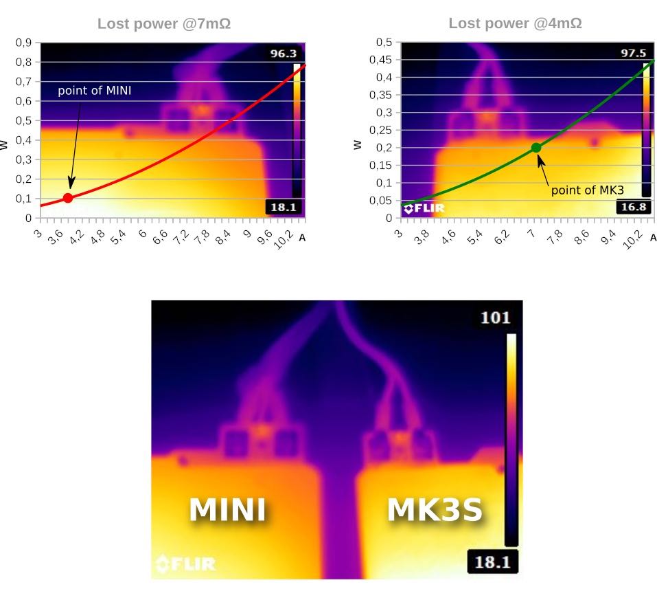
This fact is because power rises with a square of current and linearly with resistance. The normal running current of the MINI heatbed is 3.6 A, MK3S is 7 A, this makes a huge difference, For comparison, power loss on resistor for LED is 220 mW.
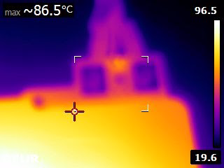
The following thermal-image shows a comparison of the LED resistor with the connection and its surroundings
Due to measured values, we can confirm that there is a slight increase in resistance but due to lower running current, we are certain that it's not an issue. We can confirm that even our oldest MINI printers from the early stages of development do not show any measurable connection resistance increase over time.
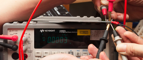
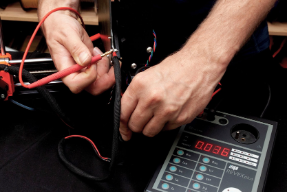
We used two different methods of measurements:
- Standard 4 wire measurement of low resistance using Keysight measuring just the connection resistance
- Specialized tester for pre-compliance testing of grid-connected devices REVEX plus measuring the whole path of one conductor from the bed connector to the copper pad (Which was showing larger values due to specification of the method and device limitations)
Measured values from method No 2:
|
Sample |
SCREW |
SCREW + WIRE | |||||||
|
QR code |
VCC / Ohm |
GND / Ohm |
Power / W |
VCC / Ohm |
GND / Ohm |
Power / W |
TOTAL / Ohm |
Power / W | |
|
MINI |
-137 |
0.004 |
0.0040 |
0.1037 |
0.0160 |
0.0160 |
0.4147 |
5.2400 |
67.9104 |
|
-160 |
0.008 |
0.0120 |
0.2592 |
0.0150 |
0.0190 |
0.4406 |
5.2100 |
67.5216 | |
|
-153 |
0.004 |
0.0050 |
0.1166 |
0.0160 |
0.0130 |
0.3758 |
5.1600 |
66.8736 | |
|
-226 |
0.012 |
0.0080 |
0.2592 |
0.0200 |
0.0160 |
0.4666 |
5.4100 |
70.1136 | |
|
-328 |
0.005 |
0.0040 |
0.1166 |
0.0130 |
0.0120 |
0.3240 |
5.1600 |
66.8736 | |
|
Average |
0.007 |
0.0066 |
0.1711 |
0.0160 |
0.0152 |
0.4044 |
5.2360 |
67.8586 | |
|
MK3S |
-205 |
0.001 |
0.0010 |
0.0980 |
0.0080 |
0.0120 |
0.9800 |
2.7500 |
134.7500 |
|
-130 |
0.004 |
0.0040 |
0.3920 |
0.0100 |
0.0120 |
1.0780 |
2.7600 |
135.2400 | |
|
-331 |
0.005 |
0.0080 |
0.6370 |
0.0160 |
0.0130 |
1.4210 |
2.7300 |
133.7700 | |
|
-333 |
0.008 |
0.0050 |
0.6370 |
0.0130 |
0.0200 |
1.6170 |
2.7000 |
132.3000 | |
|
-319 |
0.004 |
0.0040 |
0.3920 |
0.0120 |
0.0130 |
1.2250 |
2.6800 |
131.3200 | |
|
Average |
0.004 |
0.0044 |
0.4312 |
0.0118 |
0.0140 |
1.2642 |
2.7240 |
133.4760 | |
8 comments
Hi! That's why there is an emphasized note in the assembly guide about the importance of tightening the contacts properly :) If the contacts get hot, the printer will throw "preheat error bed" before starting a fire.