- Čeština
- Español
- Italiano
- Deutsch
- Polski
- Français
- 日本語
- Home
- Using the printer
- Printer maintenance
- Adjusting belt tension (MK3/MK3S/MK3S+/MK3.5/MK4)
Adjusting belt tension (MK3/MK3S/MK3S+/MK3.5/MK4)
- 3D models
- Material guide
- Slicing
- Printer maintenance
- Adjusting belt tension (MINI/MINI+)
- Adjusting belt tension (MK3/MK3S/MK3S+/MK3.5/MK4)
- Checking belt tension
- X-axis belt
- Y-axis belt
- Adjusting belt tension (XL)
- Buddy electronics Wiring (MINI)
- Changing or replacing the nozzle (MK2.5S/MK3S/MK3S+/MK3.5)
- Changing/replacing the nozzle (MINI)
- Checking/re-aligning the Bondtech gear (MK3S/MK2.5S)
- Cold pull (MINI)
- Cold pull (MK3S/MK2.5S)
- Cold pull (MK4, MK3.9, XL)
- Community translations
- CW1 maintenance
- FEP film replacement (SL1)
- Fire Suppression system (Enclosure)
- Firmware updating (CW1)
- Firmware updating (MINI/MINI+)
- Firmware updating (MK2.5S/MK2S)
- Firmware updating (MMU2S)
- Firmware updating (SL1/SL1S)
- Hotend disassembly & heatbreak stuck in the heatsink
- How to remove a stripped screw
- How to update firmware (MK3S+/MK3S/MK3)
- How to update firmware (MK4/XL)
- i3 Printer Regular Maintenance
- IPA pigment filter (CW1/CW1S)
- MMU2S regular maintenance
- MMU3 regular maintenance
- PETG sheets (Enclosure)
- Print surface preparation
- Printing without purge tower on the XL (Multi-Tool)
- Regular maintenance (MINI)
- Regular printer maintenance (MK4)
- Regular printer maintenance (XL)
- Removing filament from extruder manually
- SD cards and USB drives
- SL1/SL1S maintenance
- SL1/SL1S print removing
- Testing safety features (MK3/MK3S)
- Vibration/noise when printing (MINI/MINI+)
- Prusa Connect & PrusaLink
Loose belts would cause a printer to malfunction and prevent proper printing. It can cause Layer shifting, Ghosting, or other print abnormalities like getting an irregular shape instead of a perfect circle when printing a cylinder. The Y-axis belt is located under the heatbed, X-axis belt moves the print head. All adjustments are done with the 2.5mm Allen key.
Checking belt tension
New procedure - Belt tuner app
For checking the belt tightness using our belt tuner, follow the instructions in the video below.
Old procedure
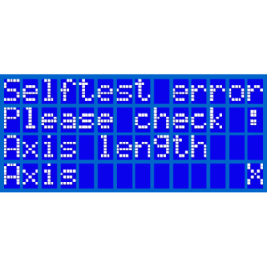
On MK3/S/+, run the Self-test or the Belt test, from Calibration on the LCD. Then check LCD-menu -> Support -> Belt-status. You want the number between 260 and 290 (275~). The lower the number, the tighter the belt is. Imagine it is a fictive count of teeth in circulation.
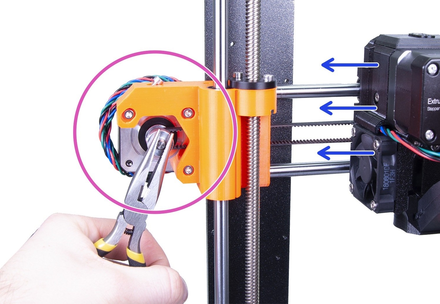
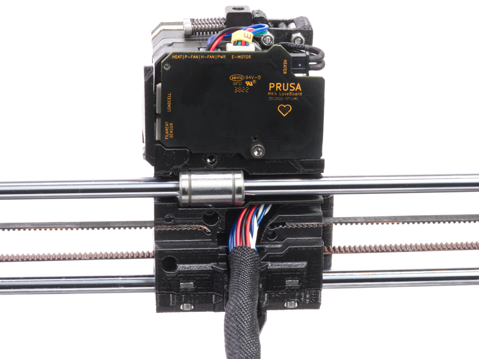
Another way is to use the technique described in this step of the assembly manual to test if the pulley is correctly tightened and if the belt is not too loose. Hold the X-axis motor shaft with pliers (take advantage of the flat part of the shaft) to fix it in place (purple circle), then try to move the extruder by hand. You should see no slack on the belt as a result of pushing on the extruder. The same procedure can be applied to test the Y-axis pulley and belt.
X-axis belt
Slight adjustments MK3S
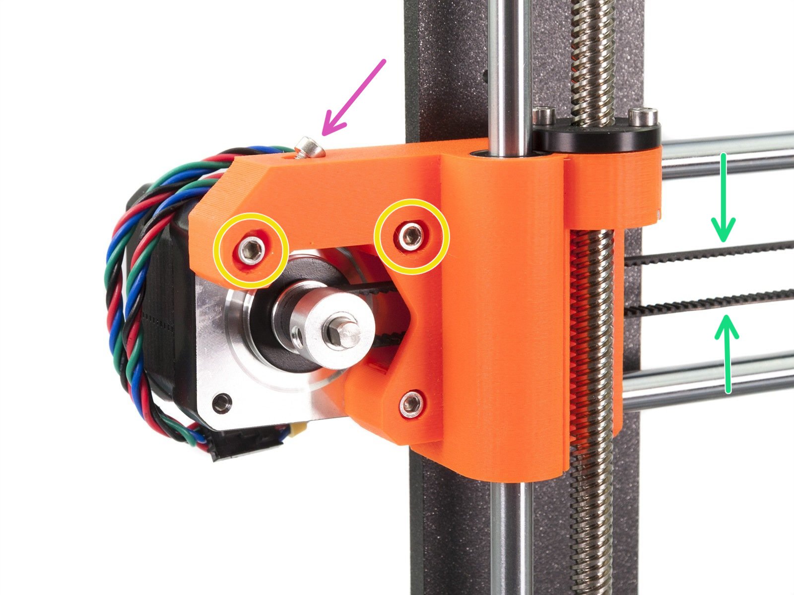
Loosen the two front-facing screws and make sure they have space to their right to move (yellow circles). While assisting with the rotation of the motor with your hand, tighten the M3x18 screw on top of the X-end-motor (purple arrow).
After each turn or two check the tension in the belt by pressing them together. For optimal performance, the belt must need some force to press together with your fingers (green arrows). Move the extruder all the way to the X-end-idler and try the belt tension in the middle of the X-axis.
Slight adjustments MK3S+, MK3.5, MK3.9, MK4
- Slightly release all the screws holding the motor, otherwise, the "tensioner" won't work as the motor must be able to move (left picture).
- Using the ball end of the Allen key, start tightening the screw on the rear side of the X-end-motor, but after each turn or two check the tension in the belt (right picture).
- When you achieve optimal tension, please tighten the screws again (left picture).
 |  |
Large adjustments MK3/S/+ or MK3.5
If a slight adjustment is not sufficient you must adjust it at the belt holder. This is found on the back of the extruder and requires a little disassembly.
First, remove the two top screws from the motor-holder to let the belt have some slack in order to easier manipulate the belt.
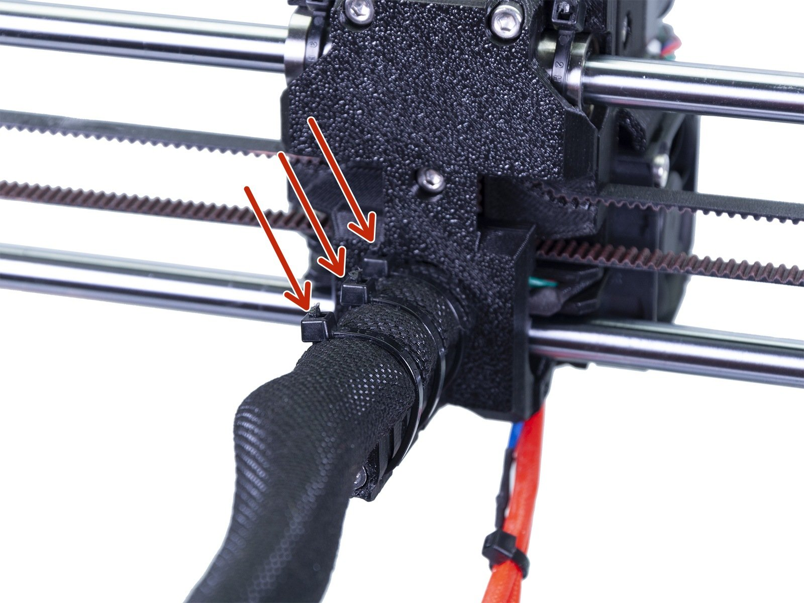
- Snip the zip-ties on the back of the extruder (red arrows), which are securing the hotend wires and the ones securing the cable wrap.
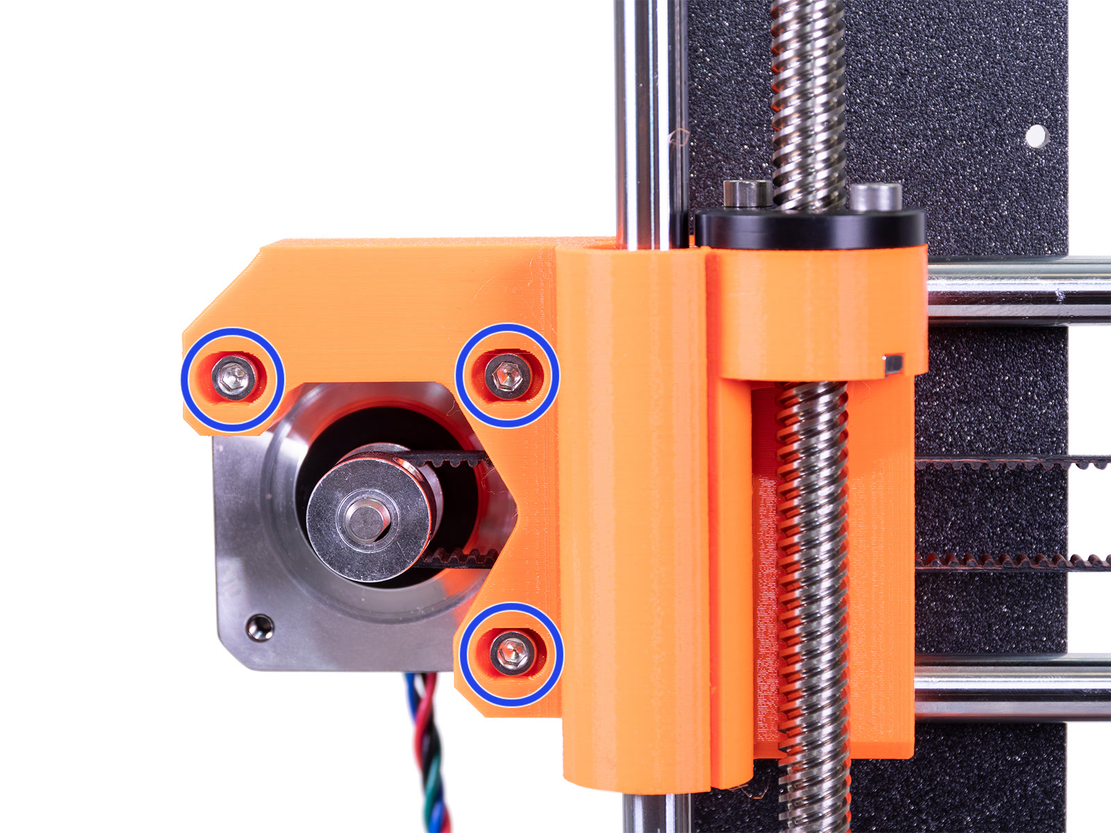
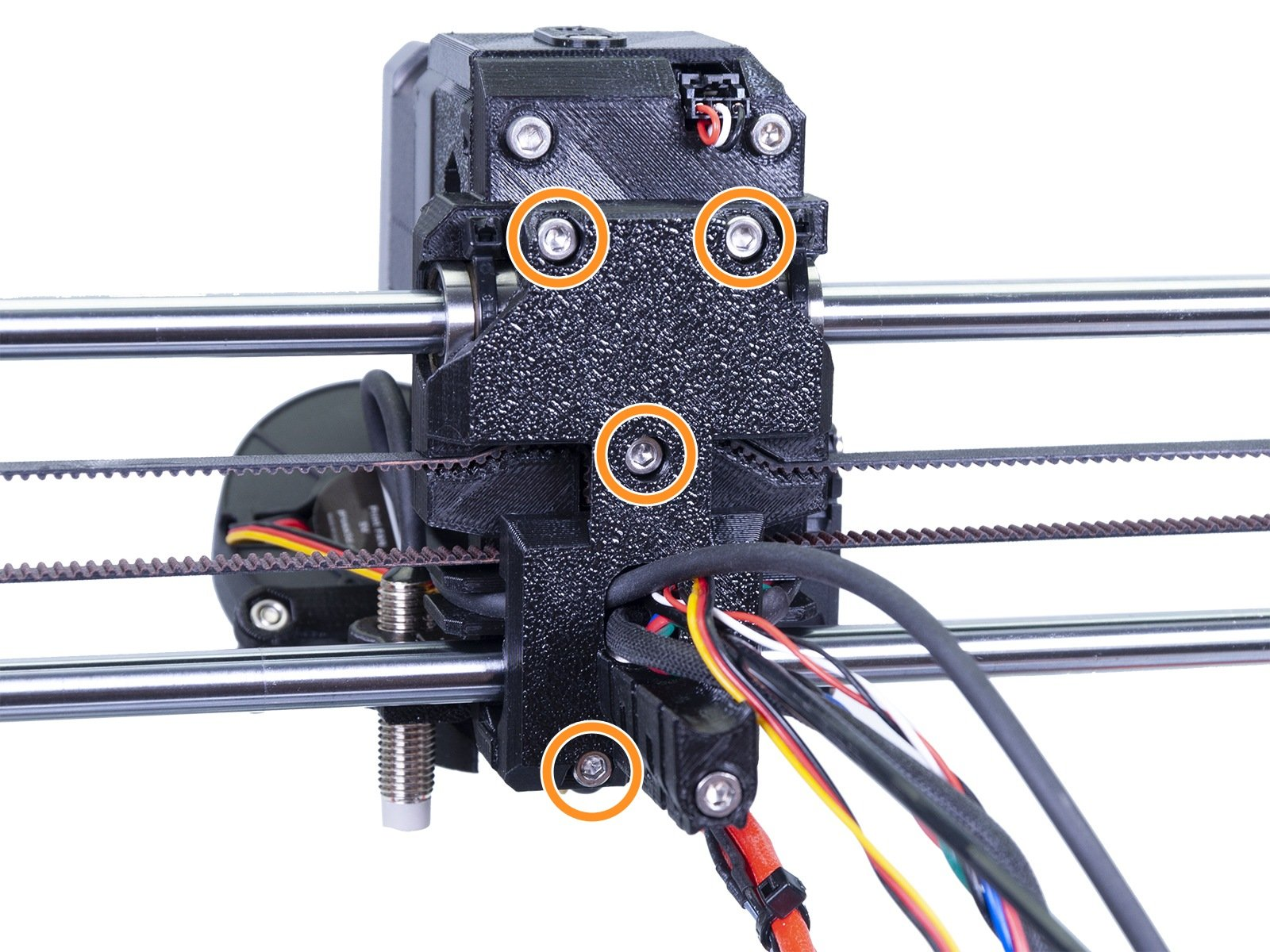
- Unscrew the 4 screws circled in the picture below.
- Carefully pull the back plate loose, making sure the wires are safe, and turn the whole plate to the left or right.
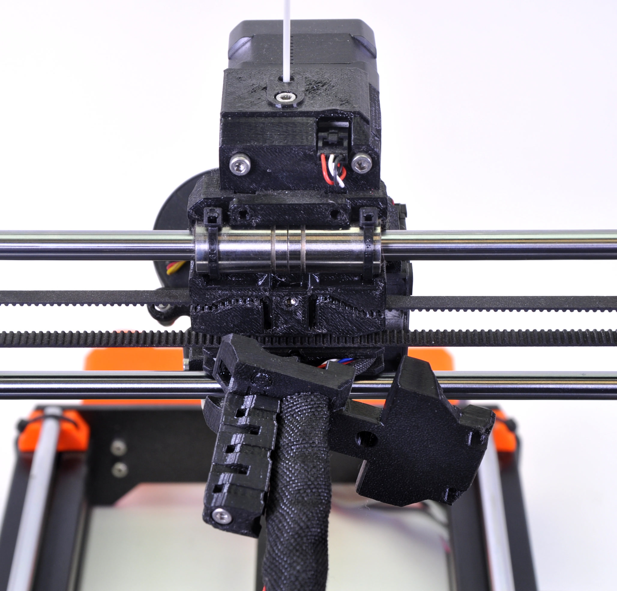
- You now have access to where you mount the belts. Put a mark on the belt with a pen or marker as close to the plastic part as possible, so you know how it was adjusted. Now, take out the belt from the mount and move it in 1-2 teeth.
- Place the back plate back on, secure the screws, starting with the center one for alignment, then put on new zip-ties.
- Re-tighten the screws on the x-motor, securing it. Adjust it tighter if needed.
Large adjustments MK3.9 / MK4
- Loosen the three indicated screws covering the X-carriage. Carefully take out the X-cover-back.
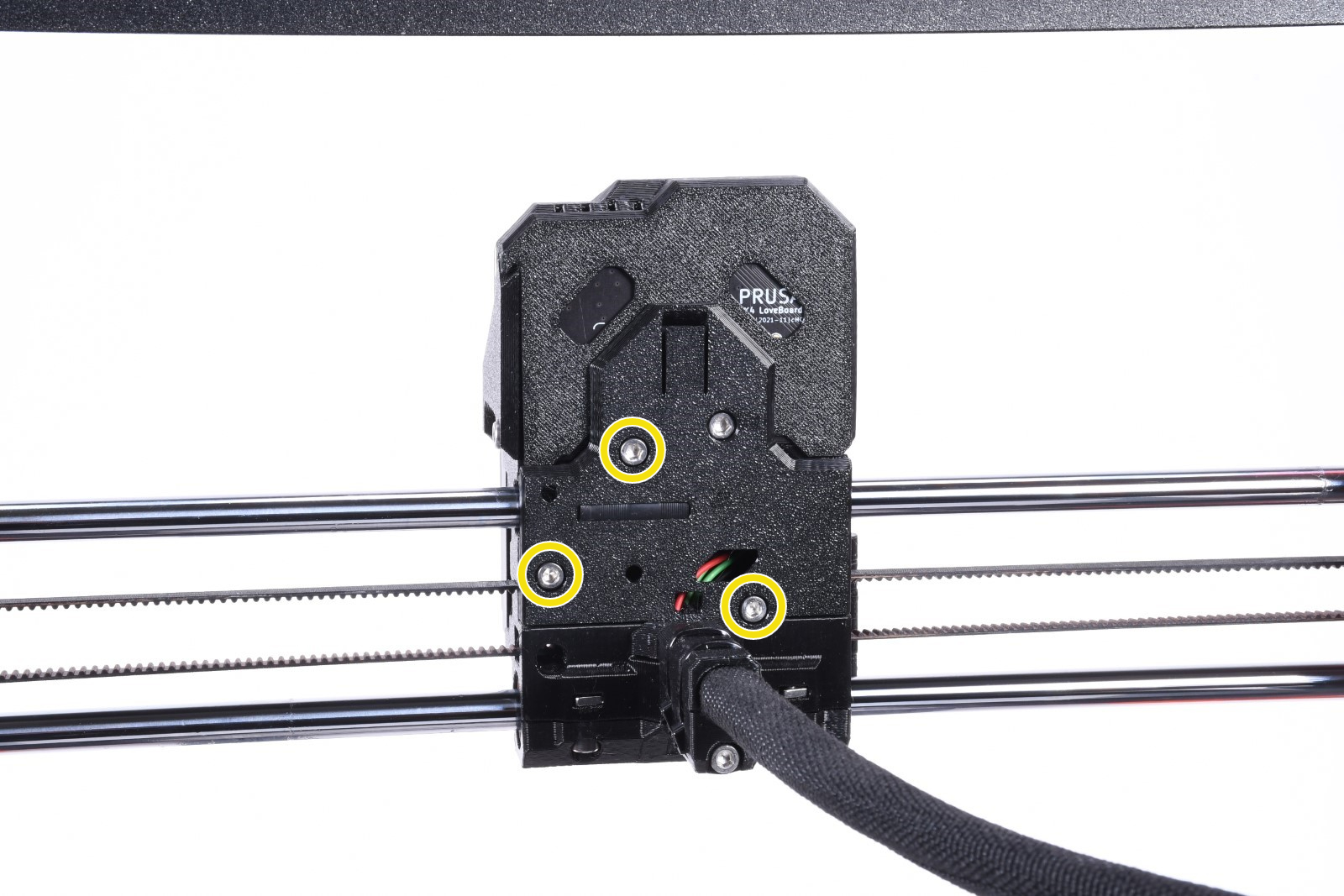
- You now have access to where you mount the belt. Put a mark on the belt with a pen or marker as close to the plastic part as possible, so you know how it was adjusted. Now, take out the belt from the mount and move it in 1-2 teeth.
Y-axis belt
Slight adjustments
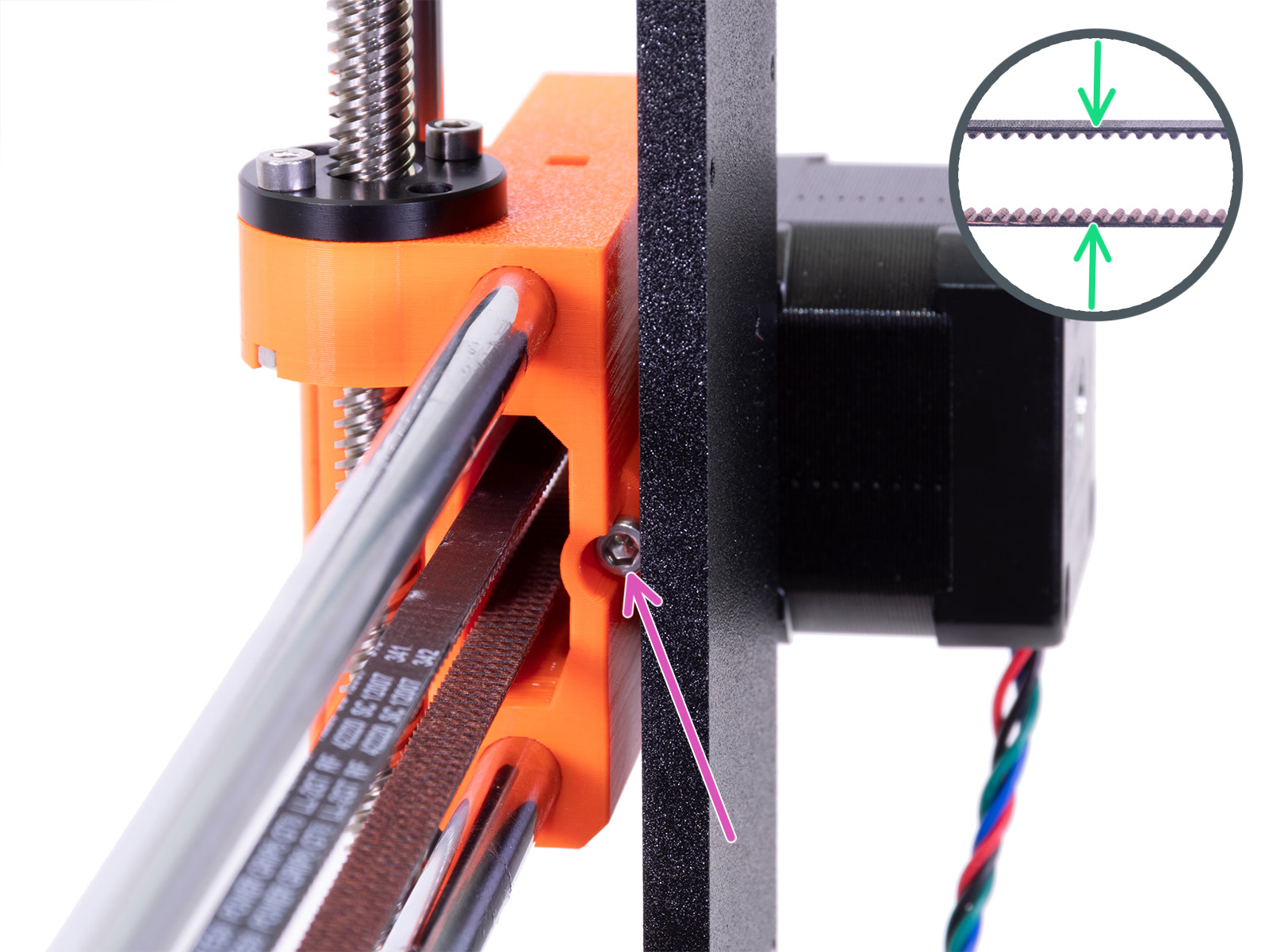
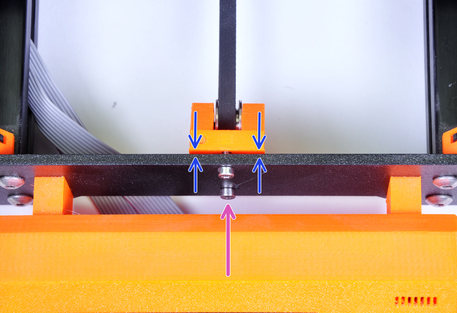
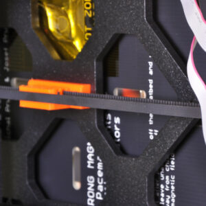
On the front plate of the printer's frame, behind the LCD module, you will find the printed Y-axis belt idler. This is held by two M3X10 screws (purple arrow), going through the front plate.
If you have a gap between the idler part and the front plate of the frame (blue arrows) you can tighten the belt by using your 2.5 mm Allen key to turn the screws clockwise (purple arrow), closing the gap.
The easiest way to access the screws is from below, by moving the printer to the edge of its table, with the LCD module sticking out. You now have access to the bolts from below the LCD module.
Large adjustments
If a slight adjustment is not sufficient you must adjust it at the belt holder. There are two main types of the Y-axis belt holder, one adjustable and one fixed. The adjustable belt holder was introduced in the first quarter of 2019, with the S-upgrade for the Original Prusa MK3, and is also featured on the Original Prusa MK4. Adjustments for this are explained in 'Method 1'. For an earlier Original Prusa MK3, follow 'Method 2', for the fixed belt holder.
Method 1 - Adjustable belt holder
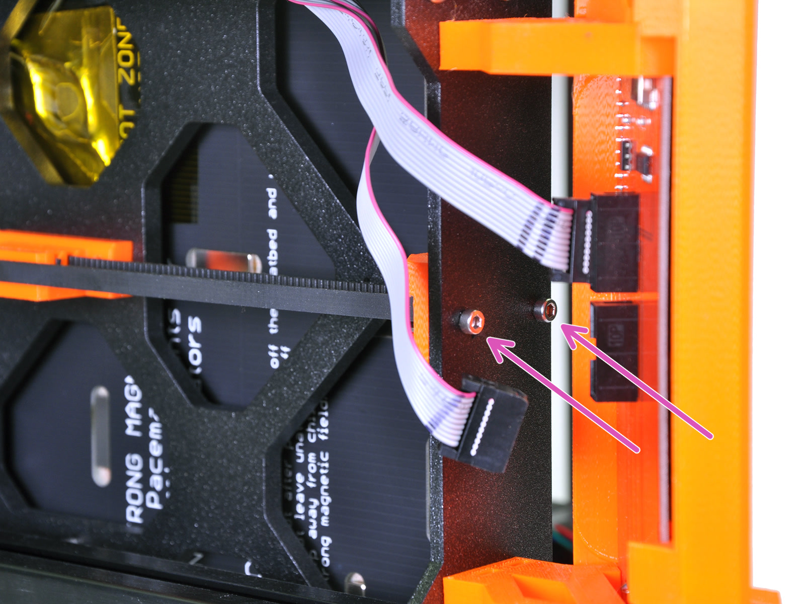
- Unplug the printer and lay it over on the side of the PSU.
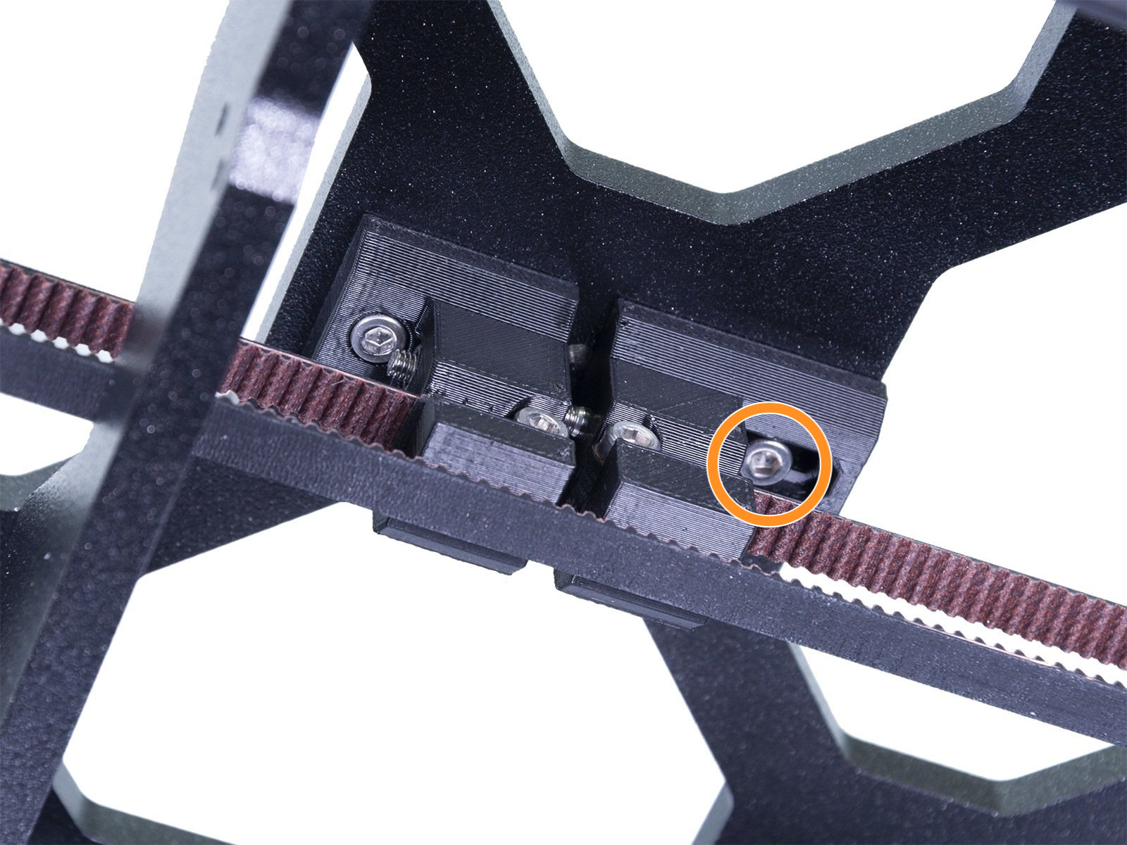
- Below the bed carriage, you will find the belt holder. Loosen the right screw by turning it counterclockwise (orange circle left picture).
- Turn the screw going through the two halves of the belt holder (purple arrow right picture). Turn clockwise to tighten the belt, moving the two halves together (blue arrows).
- When at the correct tension, secure the right half of the belt holder again by turning the screw from step 2 clockwise (orange circle left picture).
 |  |
Method 2 - Fixed belt holder
- Unplug the printer and lay it over on the side of the PSU.
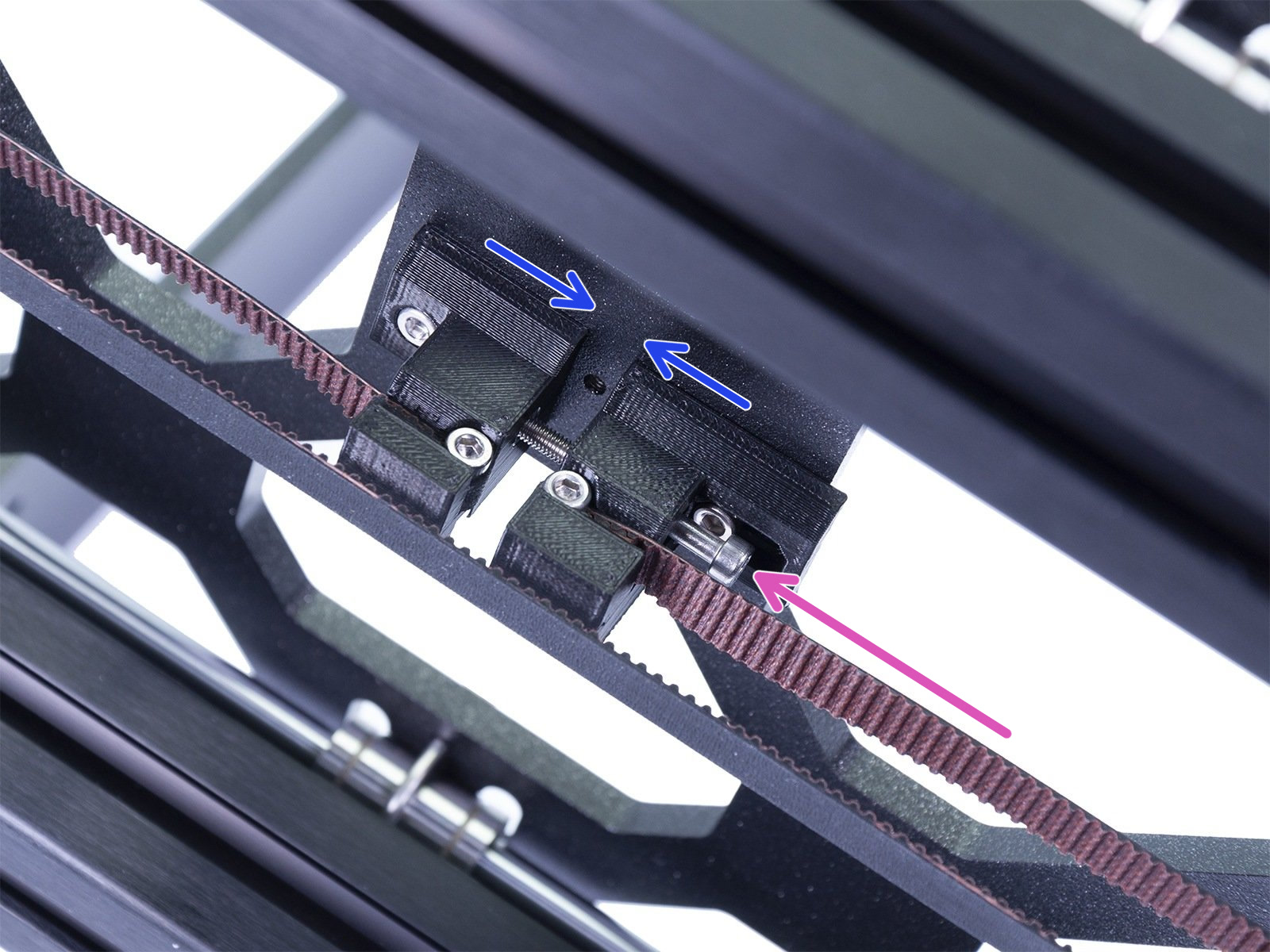
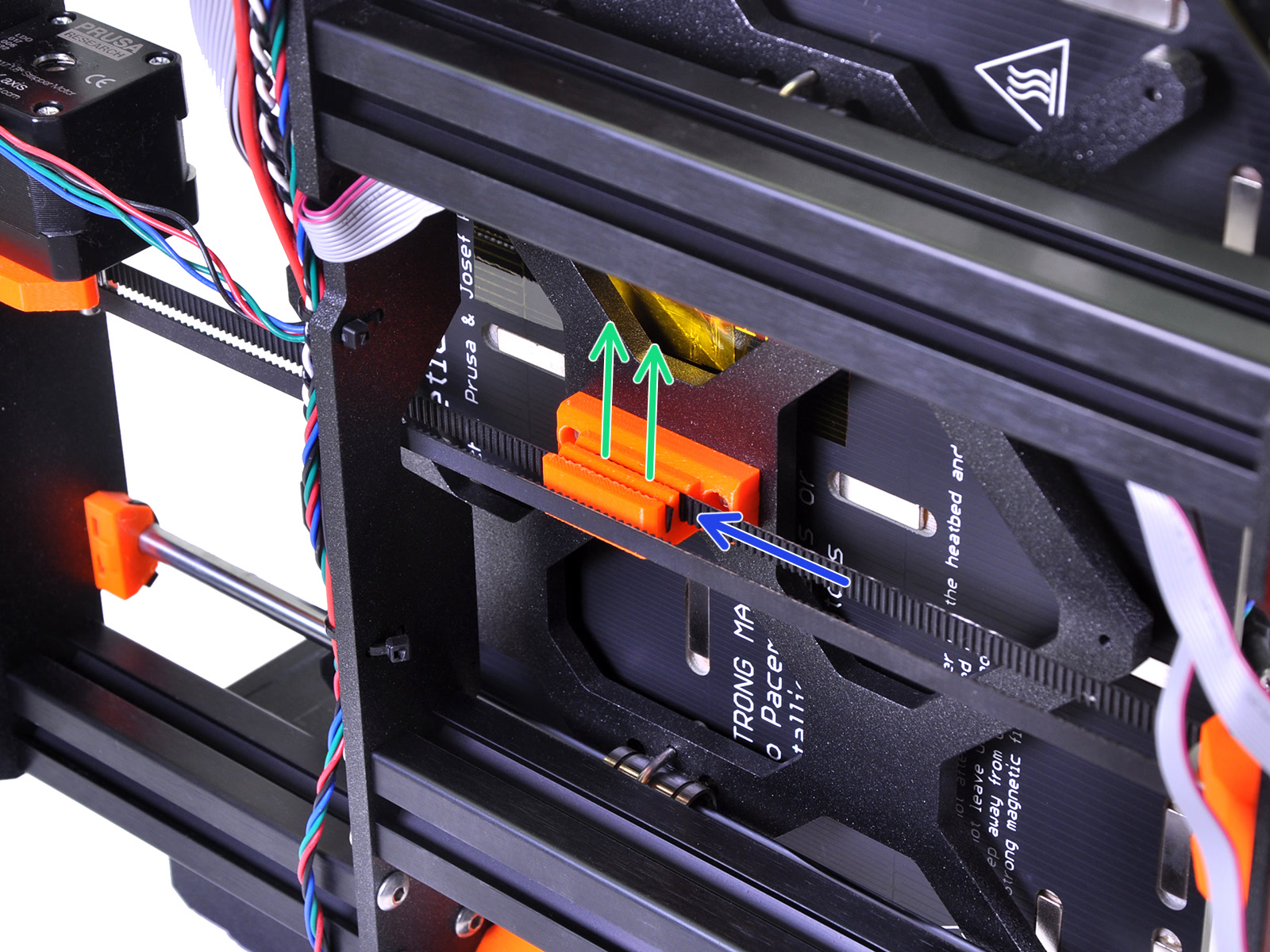
- Detach the belt-idler in order to easier manipulate the belt (purple arrows). Detaching the idler completely may not be necessary, but will make it easier to adjust the belt in the next step.
- Set a mark on the belt so you know how much you are moving it. Now take out the belt of the top slot, and move it in 1-2 teeth (blue arrow) before pushing it back into the slot (green arrows).
 Your belt mount may look slightly different, being another iteration, but the procedure remains the same.
- Re-attach the belt-idler with its two M3x10 screws through the frame (purple arrow). Leave a gap with the frame, for slight adjustments (blue arrows).
Comments


Still have questions?
If you have a question about something that isn't covered here, check out our additional resources.
And if that doesn't do the trick, you can send an inquiry to [email protected] or through the button below.