Co se stalo?
Tiskárna zobrazuje zprávu "Dlaždice vyhřívané podložky č. #: Chyba měření teploty; termistor může být vadný.".
Název chyby: MB Maxtemp Err
Kód chyby: #17253
Chybová hláška obsahuje číslo poškozené dlaždice vyhřívané podložky. Chyba může znamenat problém s termisorem připojeným k samotné dlaždici vyhřívané podložky.
Jak to spravit?
Vizuální kontrola
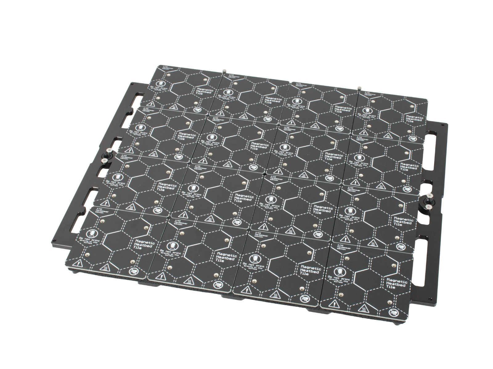
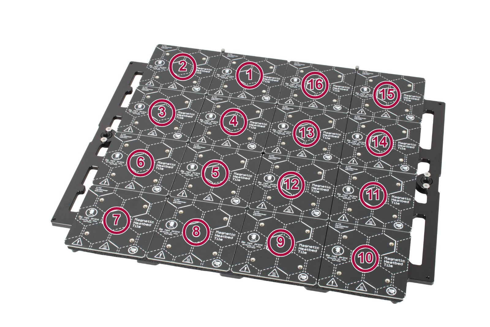
Zkontrolujte, zda není dlaždice vyhřívané podložky fyzicky poškozena, například zda není na některém povrchu dlaždice škrábanec nebo zda není na spodní straně dlaždice kabel ve špatném stavu. Určete číslo dlaždice vyhřívané podložky.
 |  |
Zkontrolujte, zda je uvedený kabel vyhřívané podložky správně spojen s elektronikou modulárního bedu a s dlaždicí vyhřívané podložky, a spojení znovu upevněte.
Chyba na dlaždicích vyhřívané podložky č. 1 nebo 7
V případě chyby konkrétně na dlaždici heatbedu č. 1 nebo 7 je možné, že je vadný jeden z napájecích zdrojů. Než se pokusíte o výměnu kabelů podle níže uvedeného schématu, zkuste provést následující kroky:
- Vypněte tiskárnu, ujistěte se, že je vychladláa odpojte ji ze zásuvky.
- Při pohledu ze zadní strany tiskárny, proveďte následující kroky: u levého zdroje napájení při chybě na dlaždici 1 a pravého zdroje napájení při chybě na dlaždici 7.
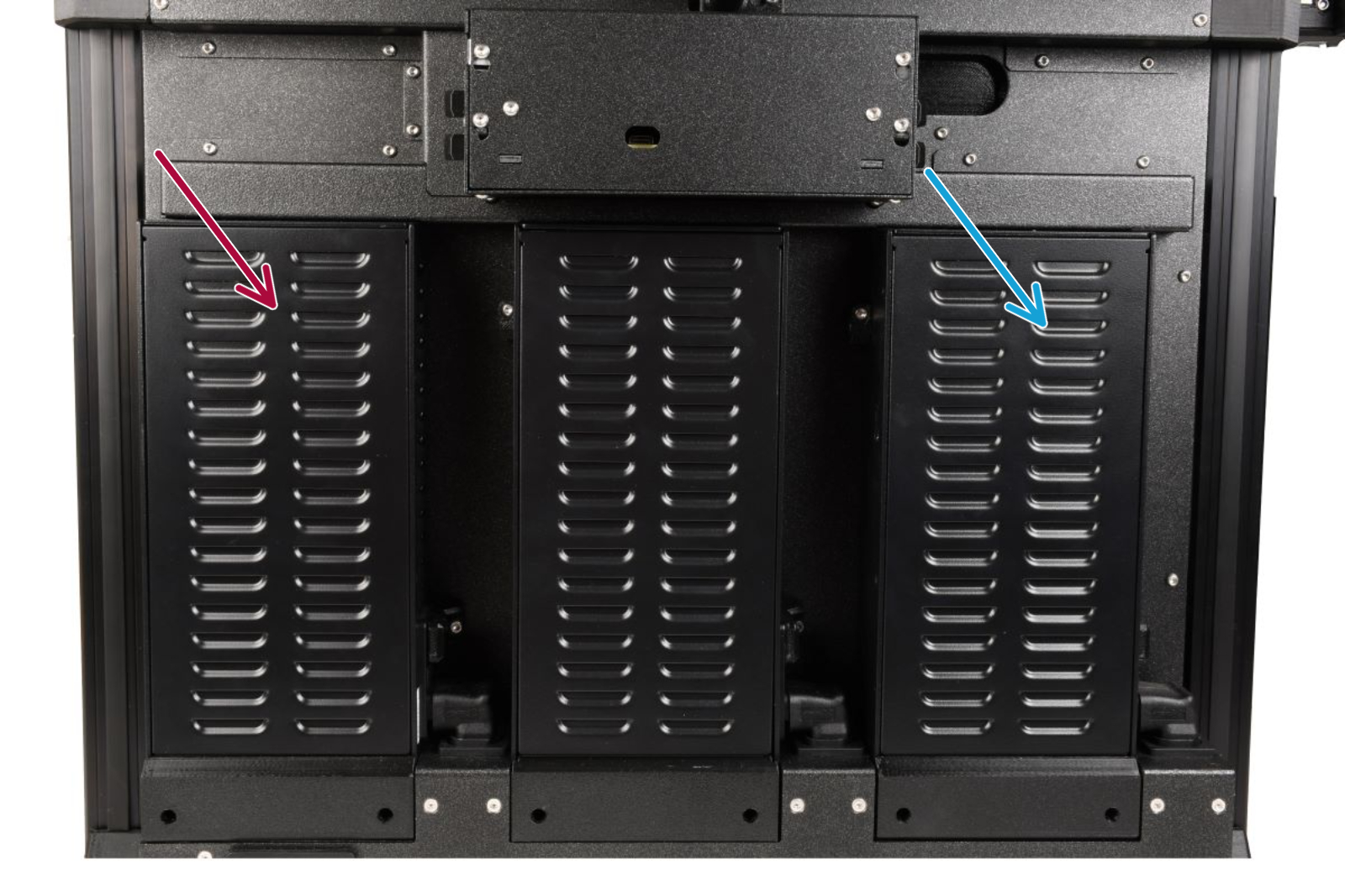
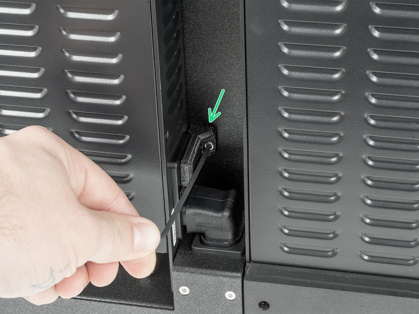
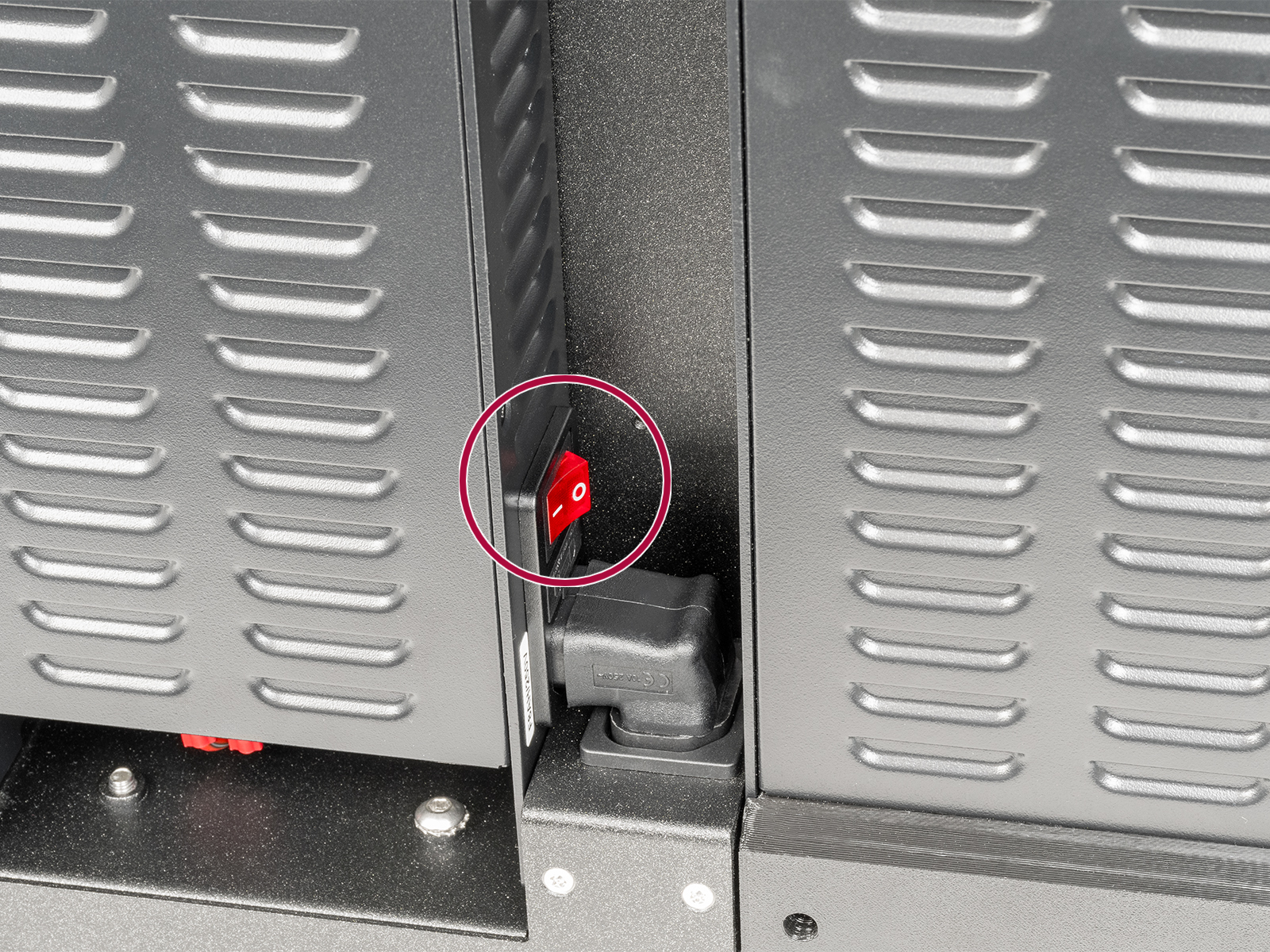
- Pomocí 2,5mm inbusového klíče odstraňte šroub, který drží kryt spínače. Po jeho vyjmutí zkontrolujte, zda je zdroj napájení zapnutý (symbol "I").
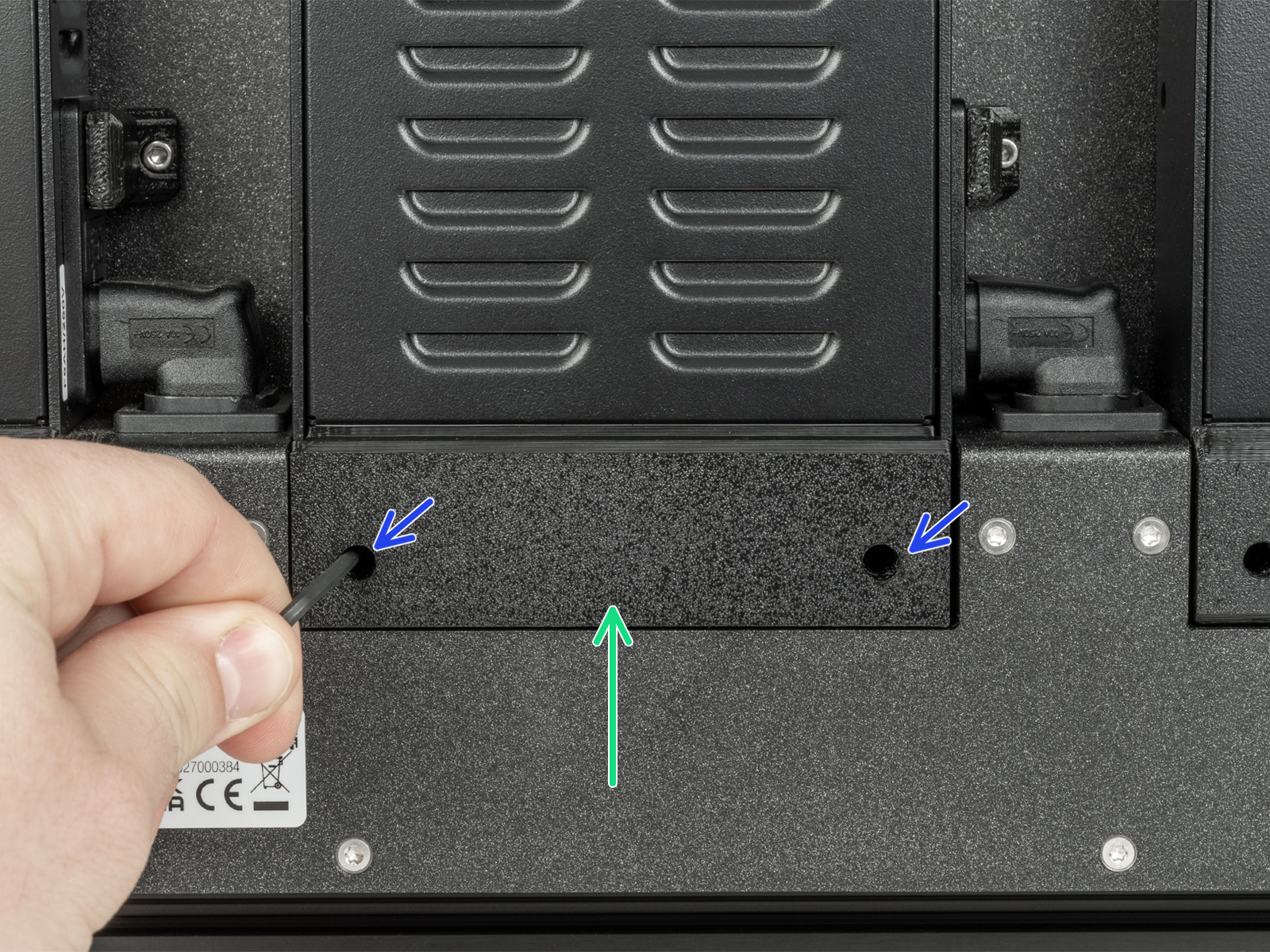
- Pomocí 2,5mm inbusového klíče odstraňte dva šrouby upevňující kryt zdroje napájení. Poté kryt sejměte..
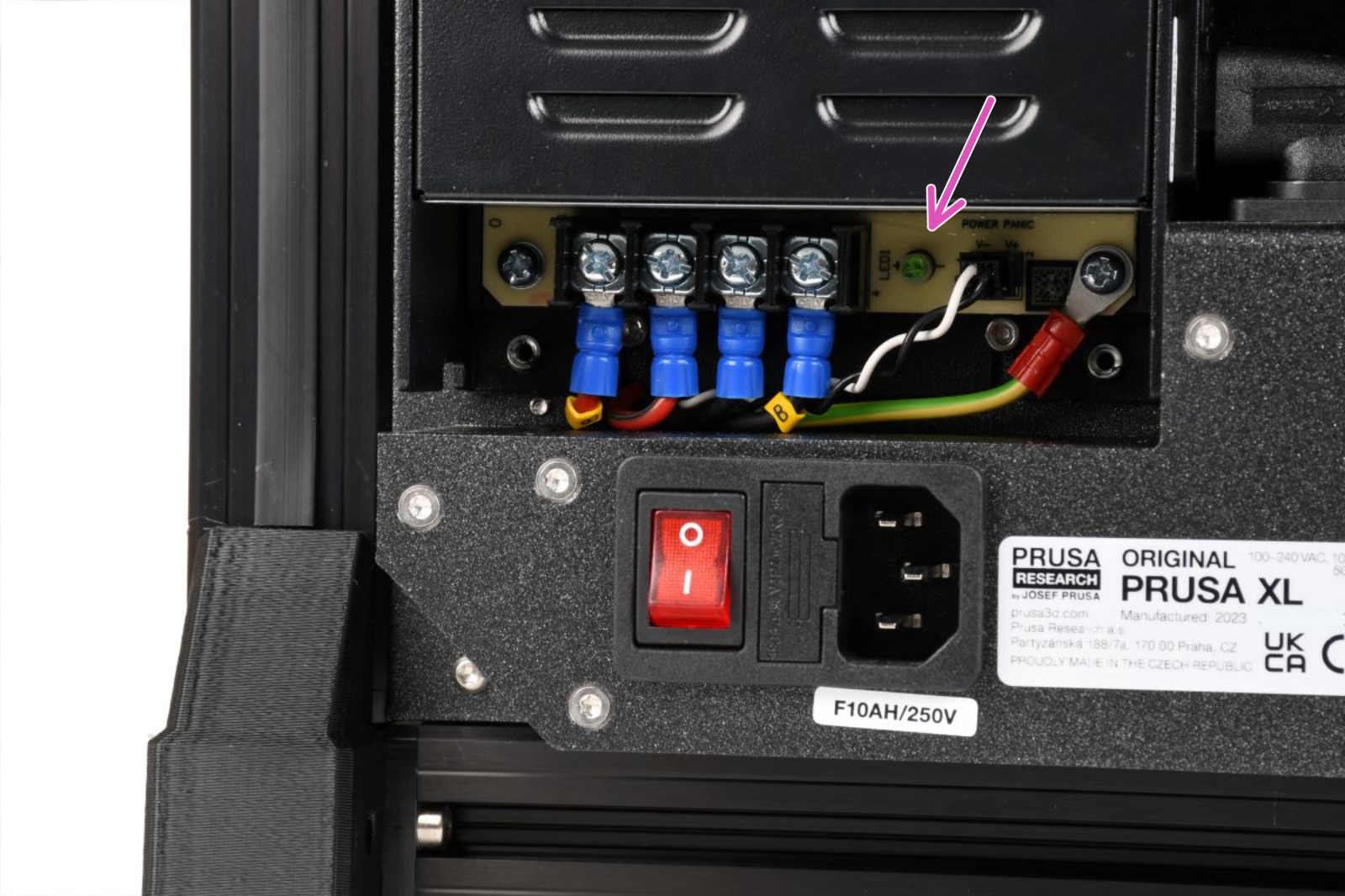
- Zapněte tiskárnu. Zkontrolujte, zda se zelená kontrolka rozsvítí, nebo zůstane zhasnutá. Zelená kontrolka napájení, která zůstává po zapnutí tiskárny zhasnutá, znamená problém se zdrojem napájením.
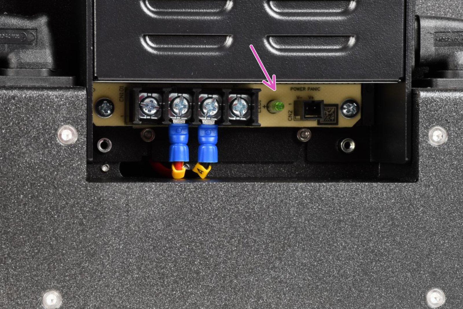
Levý zdroj napájení Pravý zdroj napájení
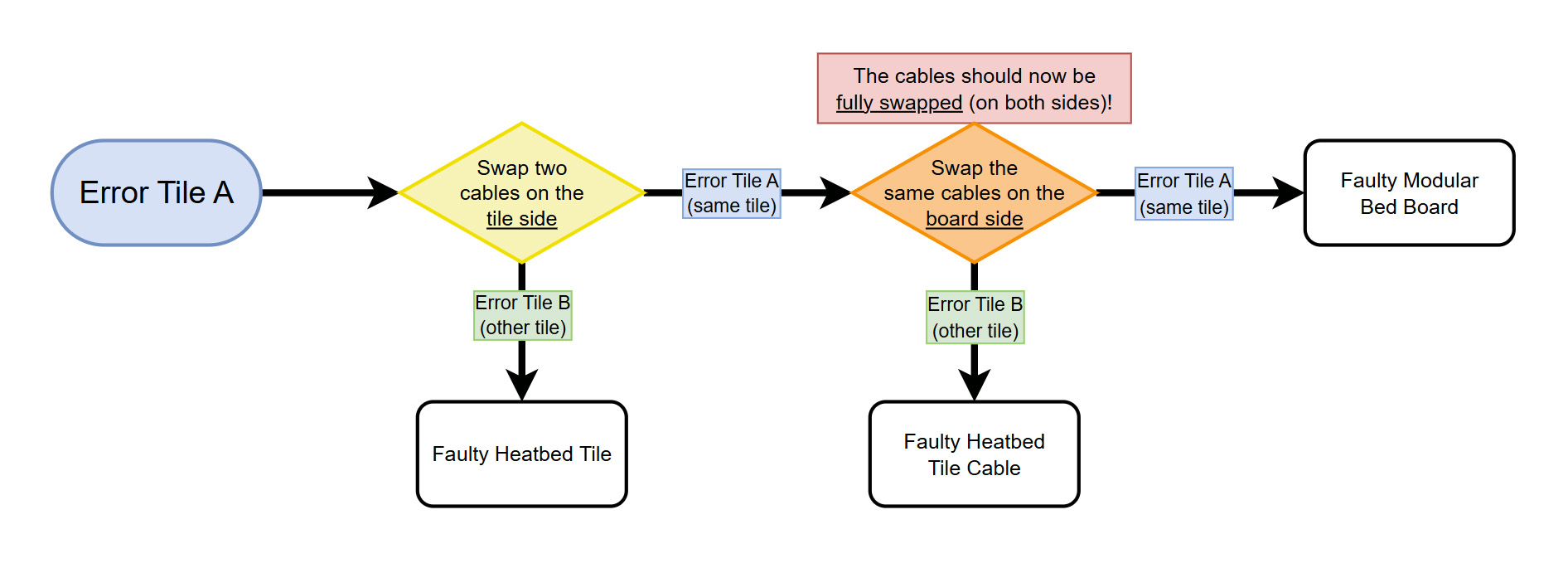
Schéma řešení problémů
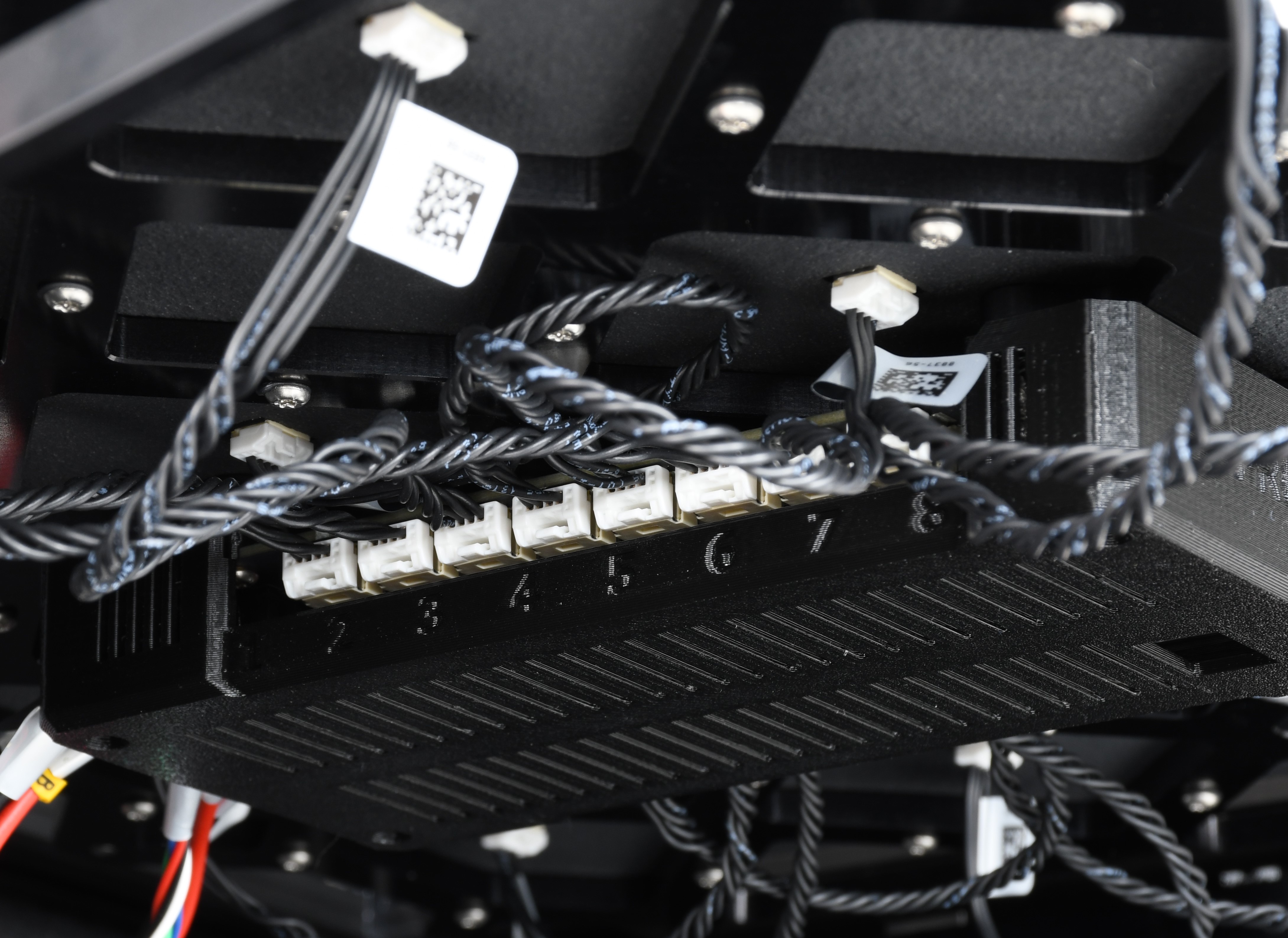
Při diagnostice vadné součástky postupujte podle níže uvedeného schématu. Nejprve vyměňte vodič na straně dlaždice připojený k vadné dlaždici za jakýkoli jiný vodič na straně dlaždice.
Každý konektor má bezpečnostní západku. Před odpojením je nutné západku stisknout. Jinak by mohlo dojít k poškození konektoru.
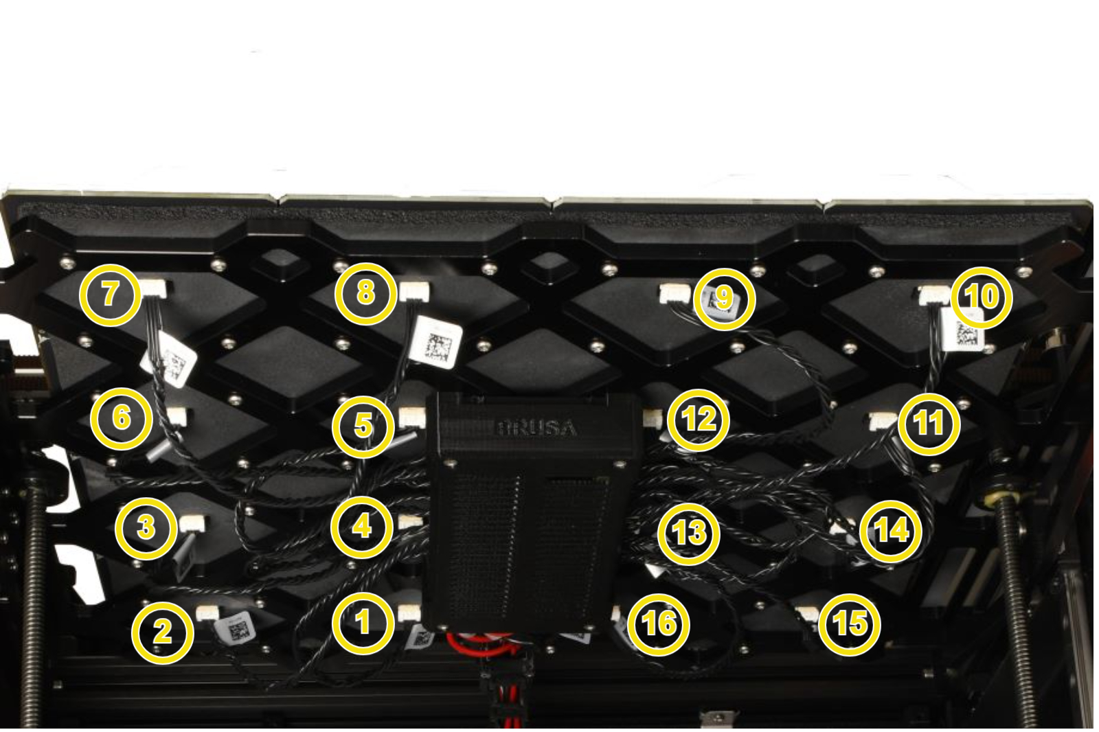 | 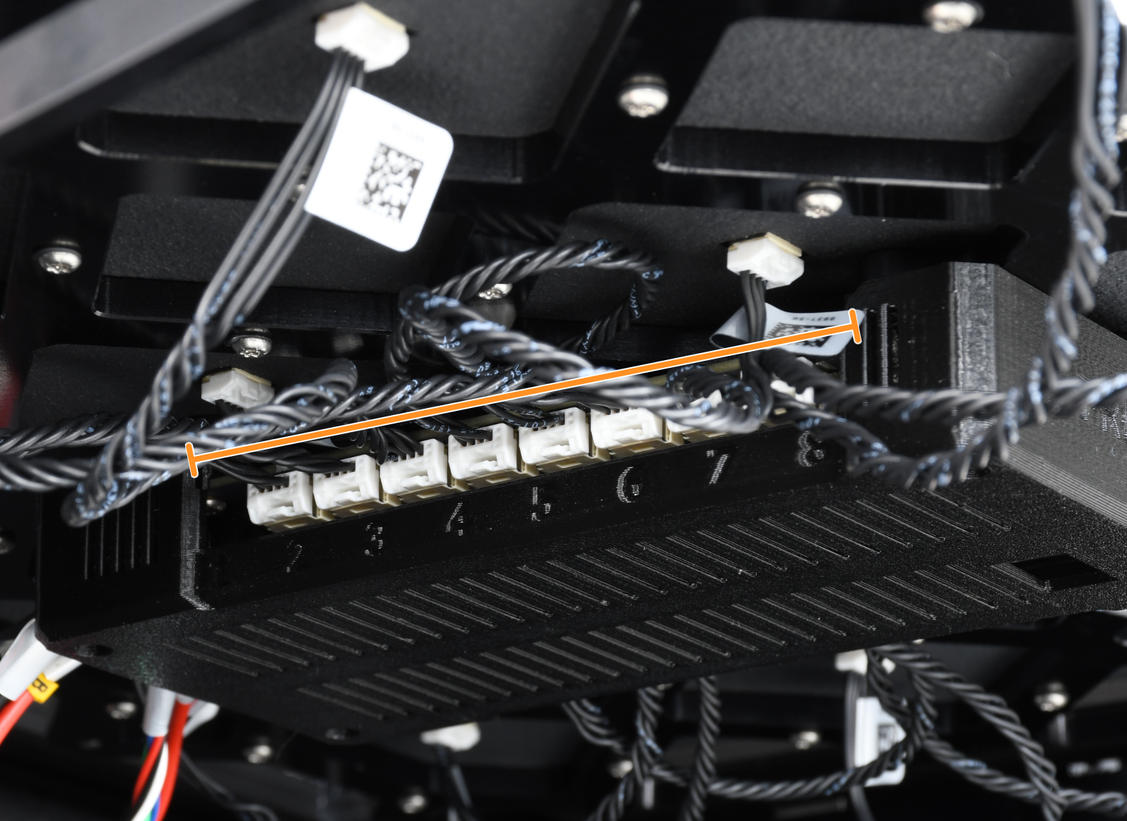 |
| Zapojení konektorů na straně dlaždic vyhřívané podložky. | Zapojení konektorů na straně desky. |