What happened?
The printer is showing the text "Unable to home the printer. Do you want to try again?"
Error name: Crash recovery home fail
Error code: #31812 (CORE One) #35812 (CORE One L) #26812 (MK4S) #13812 (MK4) #27812 (MK3.9S) #21812 (MK3.9) #28812 (MK3.5S) #23812 (MK3.5) #17812 (XL) #12812 (MINI)
How to fix it?
Check for obstacles
Ensure the path of the X and Y axes is free. A common obstacle could be debris or filament strands from a previous print.
Check the smooth rods or linear rail
Ensure there are no rough spots on the smooth rods or linear rail. If you lubricate the smooth rods or linear bearings, beware! The lubrication type for each component is different and can be damaging if the wrong type is used. Below are the dedicated guides for either type.
- Smooth rods
- Linear rail (only present in XL, CORE One, and CORE One L X-axis)
Check the belt tension
In general, the belt may loosen over time. A slight loosening during a print could cause the warning message.
To check and adjust the belt tension, follow the guidelines from the dedicated belt adjustment guide for your printer model.
Check your X/Y axis motors and pulleys
If one of the motor pulleys loosens over time, it will misalign and contribute to inconsistent movement. The pulleys are positioned differently on each of the two XY motors. Each motor pulley has two set screws, one of which has to be aligned with the flat part of the motor shaft.
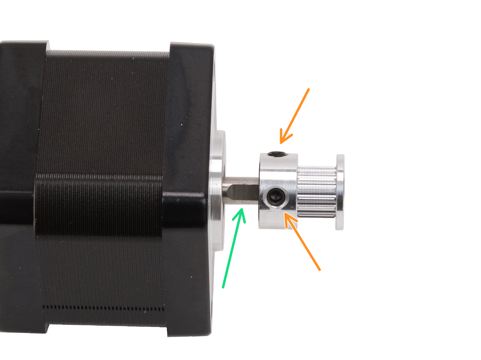
Note that the pulley position and orientation can vary across printers and their motors.
CORE One, CORE One L
The pulleys are positioned differently on each of the two X and Y motors. Looking from the front of the printer:
- Left
- The teeth for the belt are above the set screws.
- Right
- The teeth for the belt are below the set screws.
 |  |
XL
The pulleys are positioned differently on each of the two XY motors. Looking from the front of the printer:
- Left
- Note the orientation of the pulley. The teeth for the belt are below the set screws.
- The pulley is 2.5mm higher than the start of the flat part of the motor shaft. Use the 2.5mm Allen key for reference.
- Alternatively, measure the distance between the beginning of the motor shaft and the pulley, 3.6mm.
- Right
- Note the orientation of the pulley. The teeth for the belt are above the set screws.
- The pulley is flush with the top edge of the motor shaft.
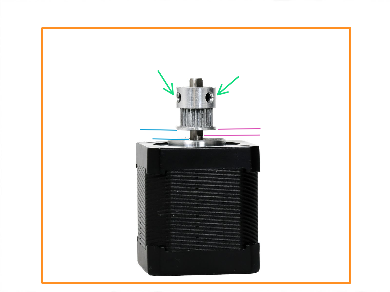 |  |
MK4/S, MK3.9/S
- Check the belt pulleys on the X and Y motor shafts. One of the set screws must be firmly tightened over the flat part of the motor shaft, there should be a small gap between the motor and the pulley, and they need to be in the correct orientation and position.
 |  |
| Correct X-axis pulley orientation and position. | Correct X-axis pulley orientation and position. |
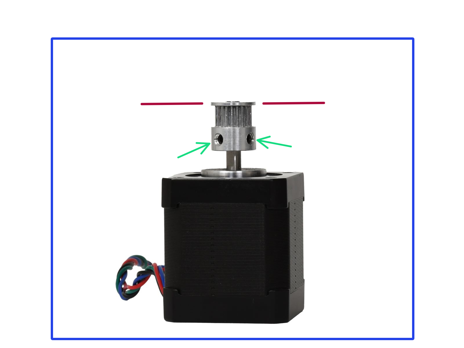
 |  |
| Correct Y-axis pulley orientation and position. | Correct Y-axis pulley orientation and position. |
MK3.5/S
Refer to the pictures below to check the pulley orientation and position. Ensure that there is a small space between the pulley and the motor, that one of the set screws is aligned with the flat part of the motor shaft, and that the other set screw is also reasonably tight.
 |  |
| Correct X-axis pulley orientation and position. | Correct Y-axis pulley orientation and position. |
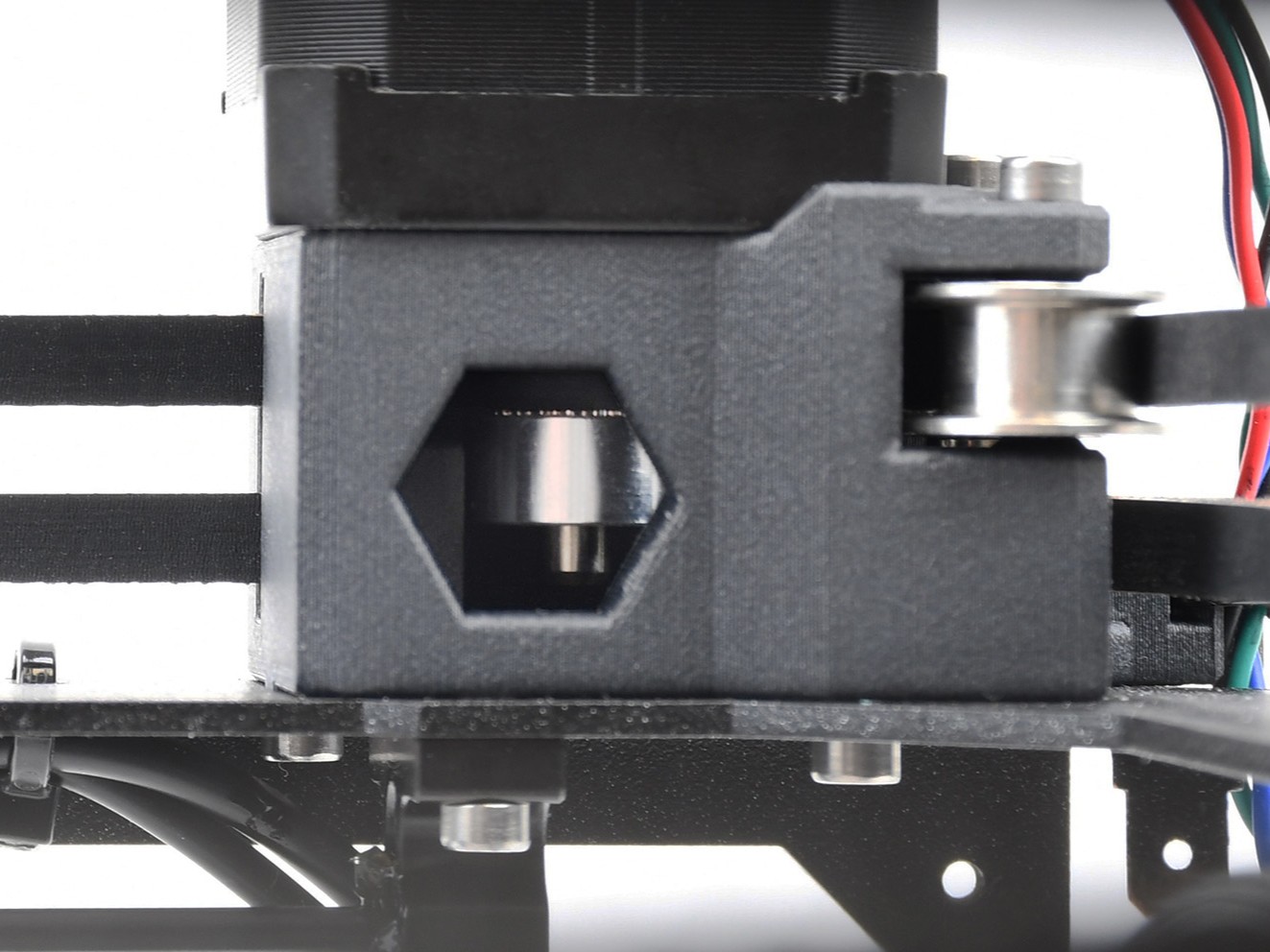
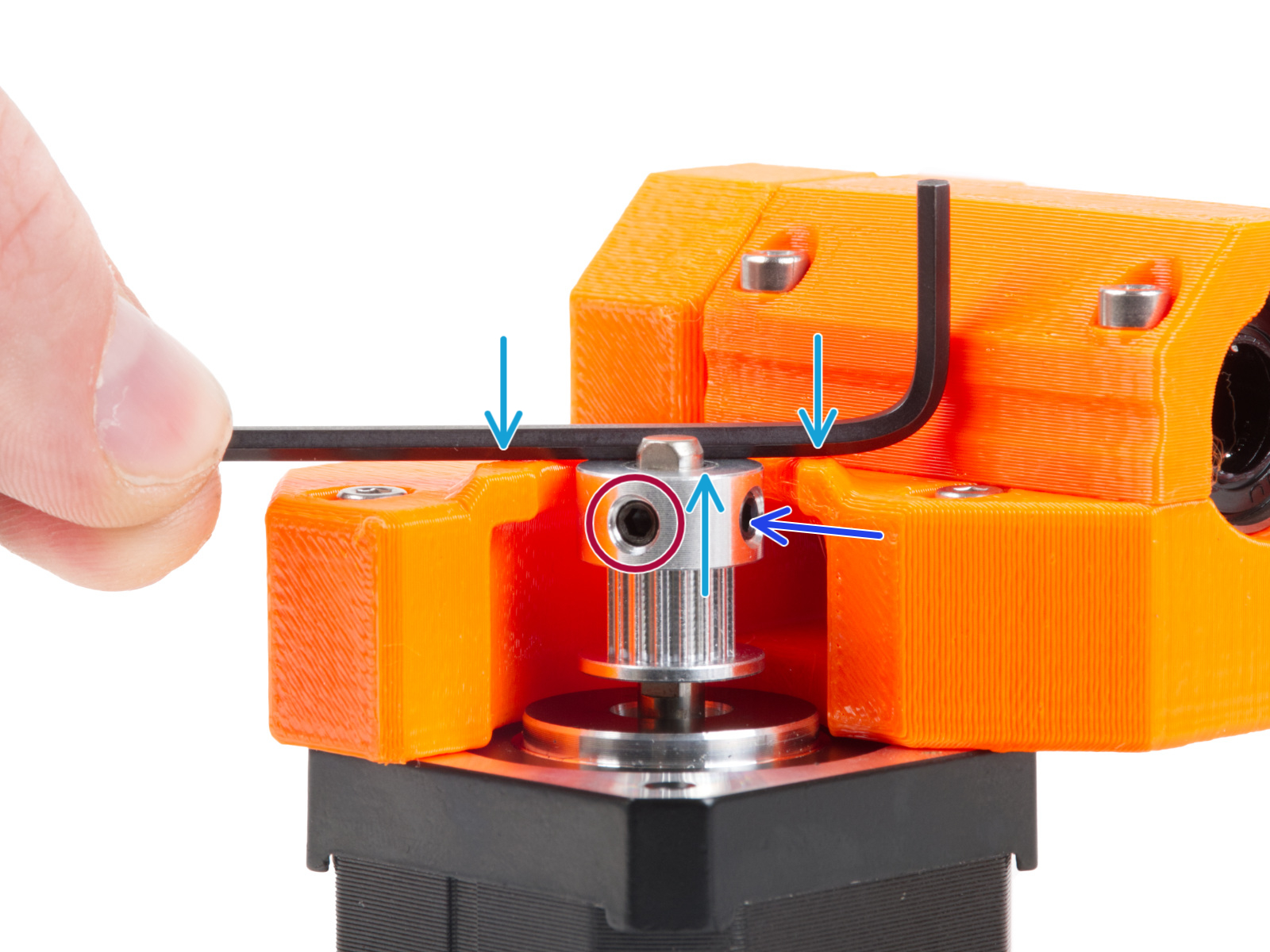
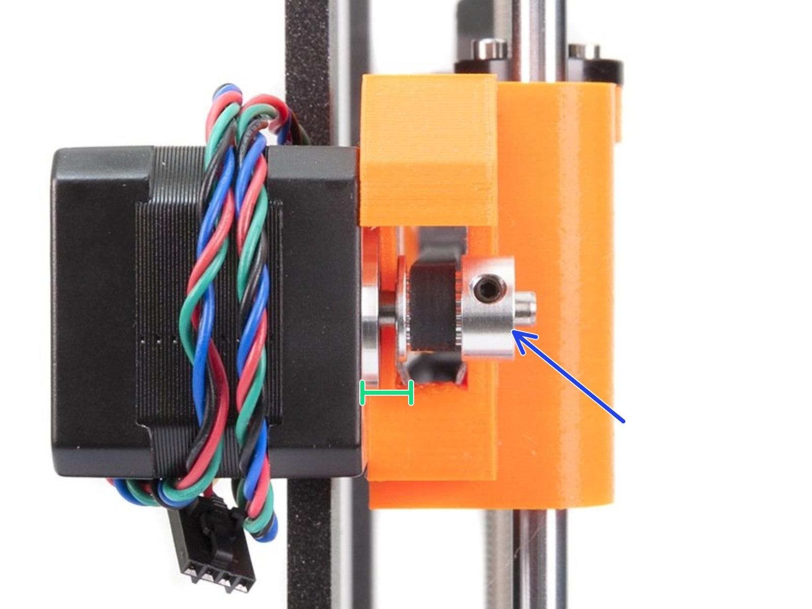
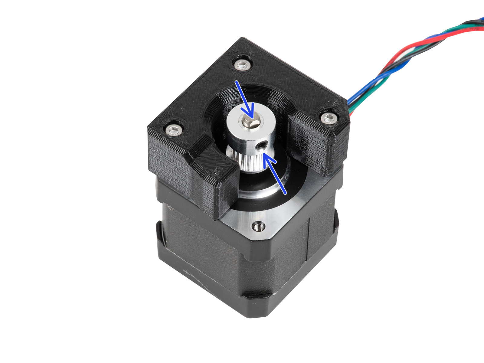
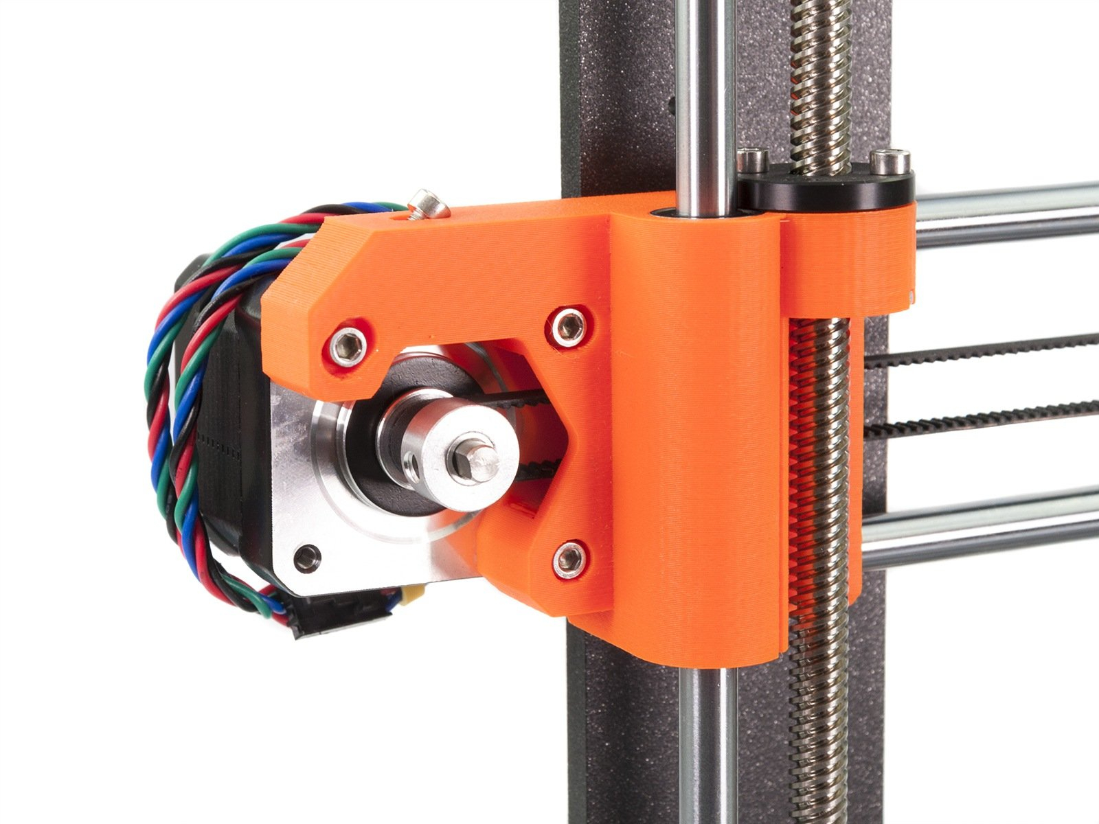
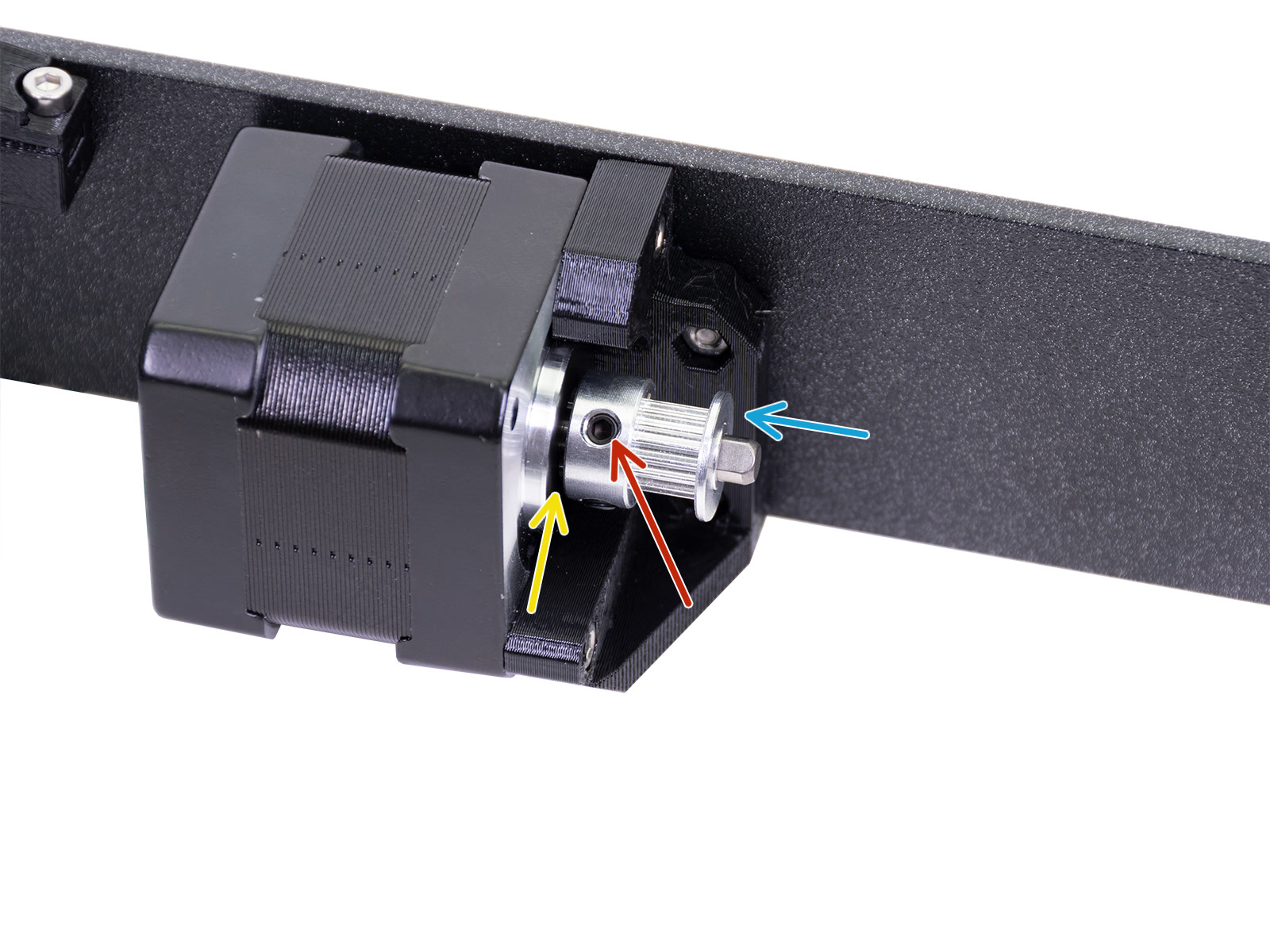
MINI/+
Check the Y-axis motor pulley to match the orientation and position from the picture below. The pulley has two set screws, ensure that one of the two set screws is aligned with the flat part of the motor shaft. Make sure the other set screw is also tightened, not excessively, and that there is a small space between the pulley and the motor.

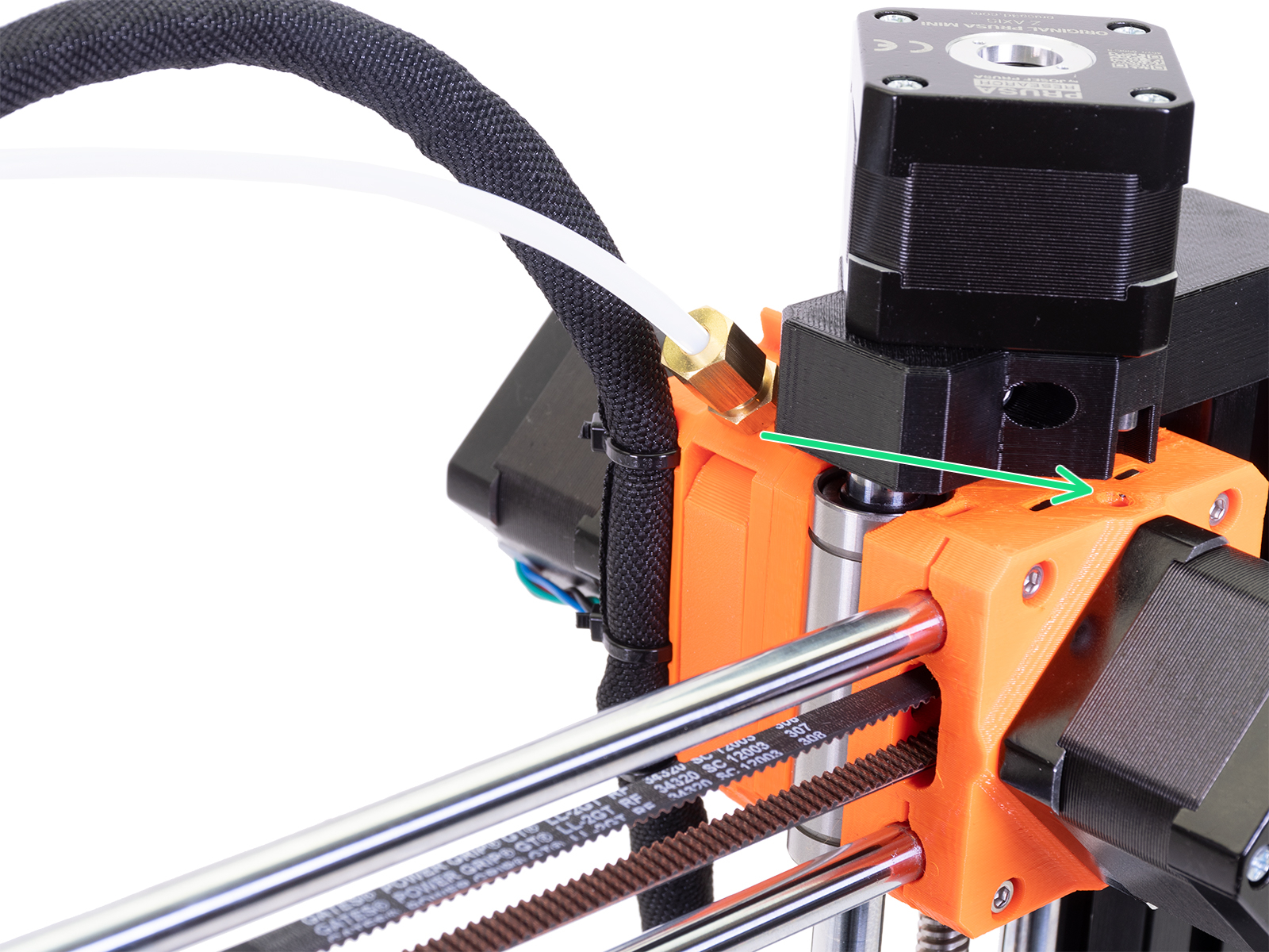
It is possible to check whether the X-axis pulley is tight from an inspection hole. However, in some cases, to verify and regain alignment between one of the set screws and the flat part of the X-axis motor shaft, partial disassembly might be needed. Below are the steps to follow, should this disassembly be necessary.
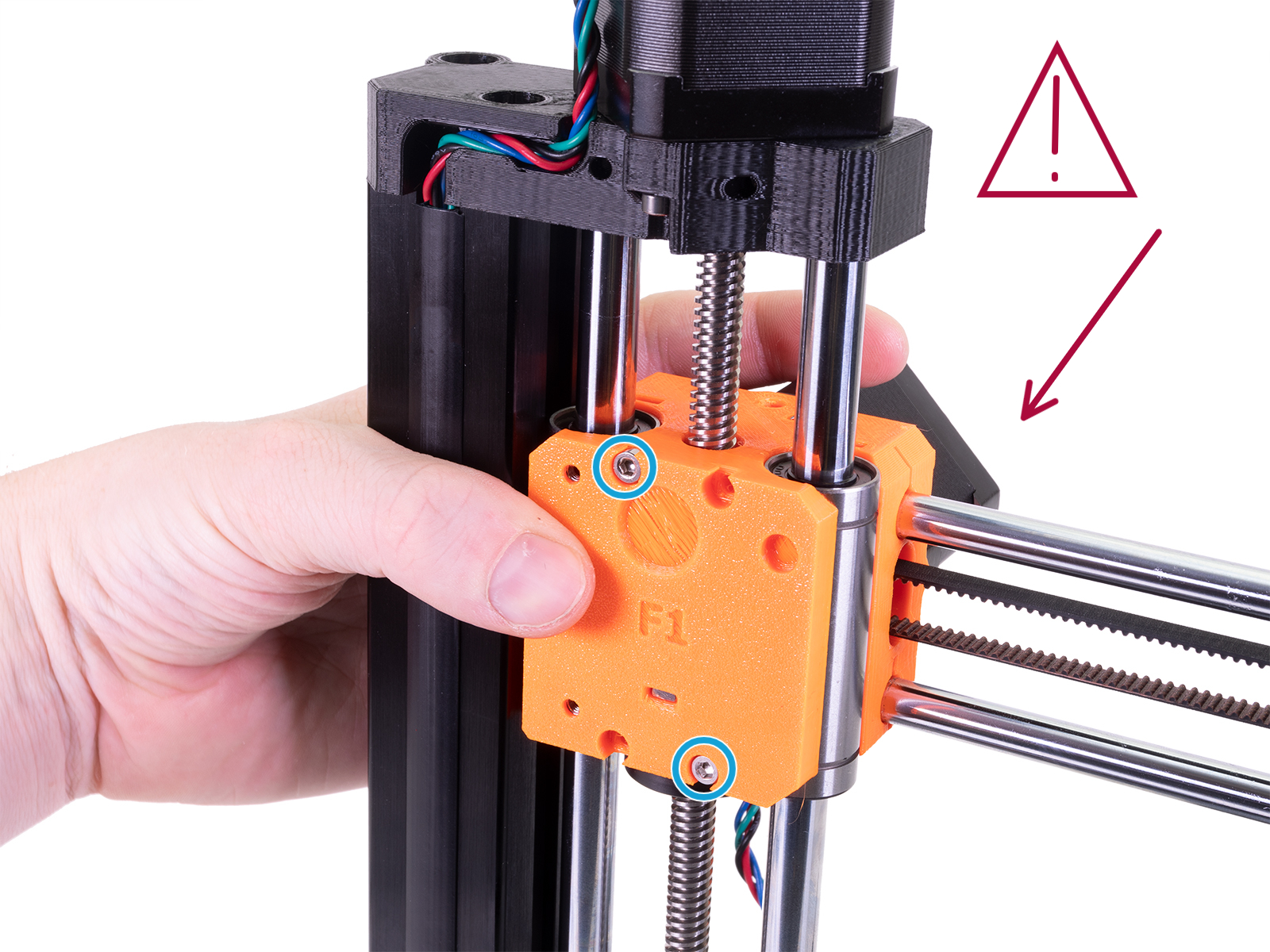
- Loosen the upper M3x25 screw. The inspection-door might come loose, remove it temporarily.
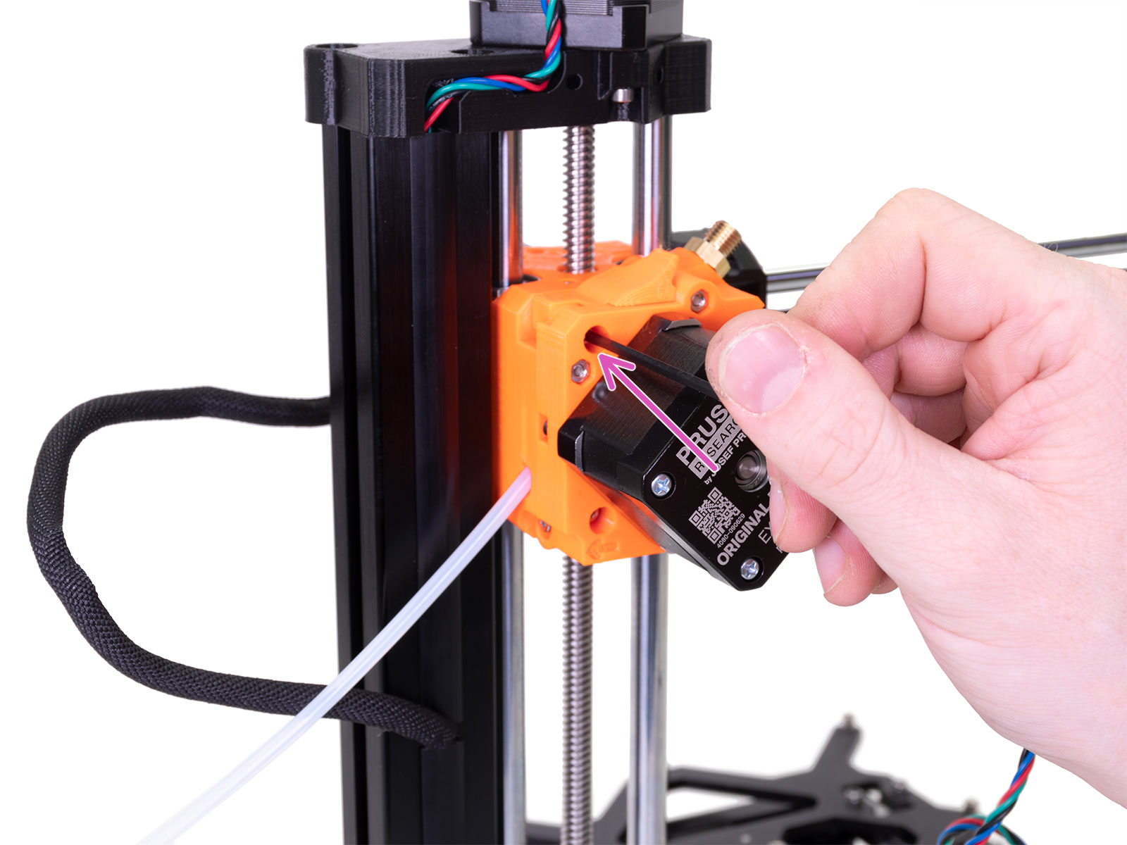
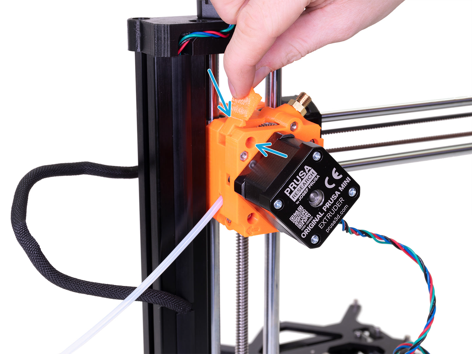
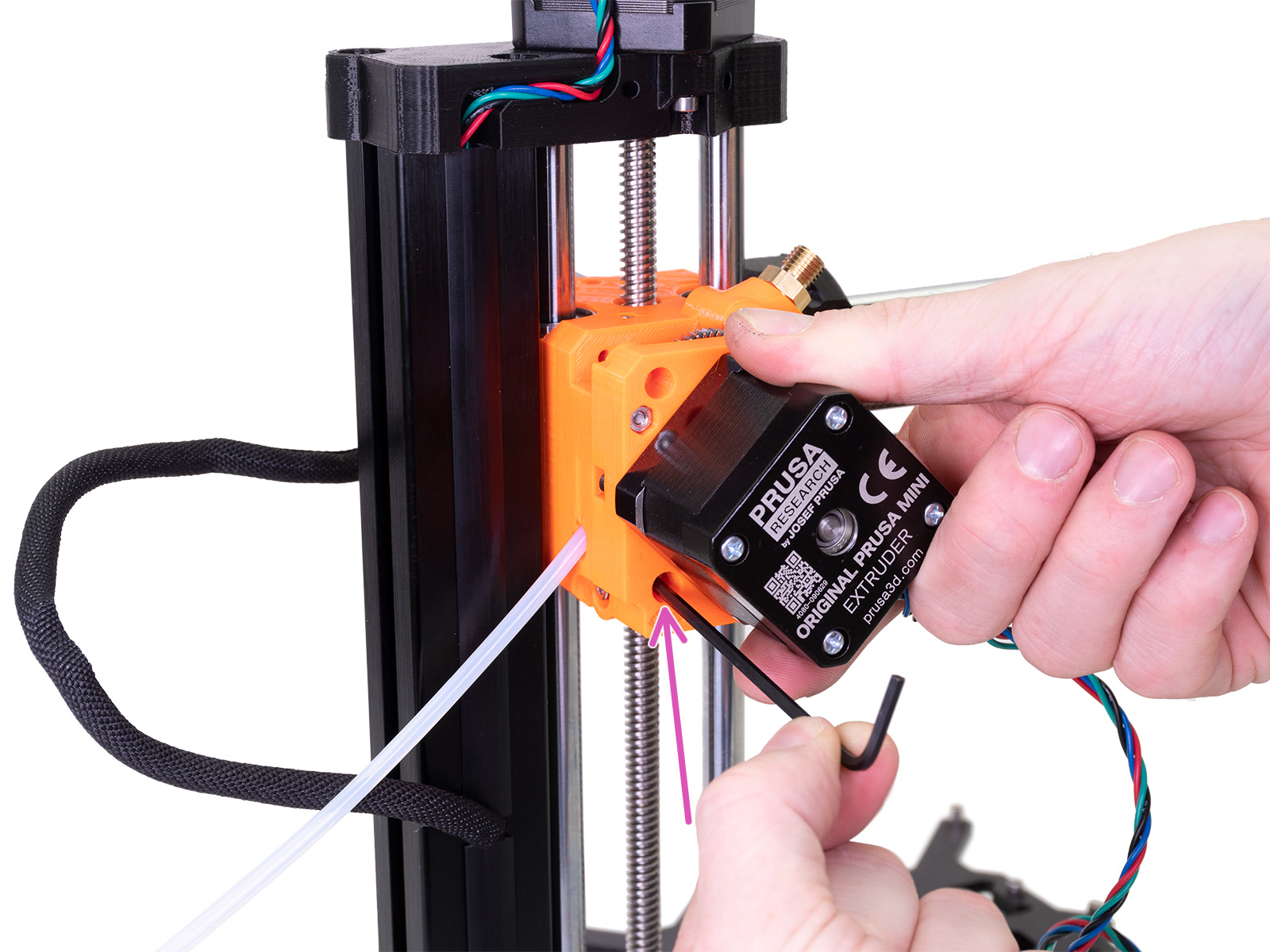
- Hold the parts with your free hand! Loosen the lower M3x25 screw, and remove the extruder block.
 | 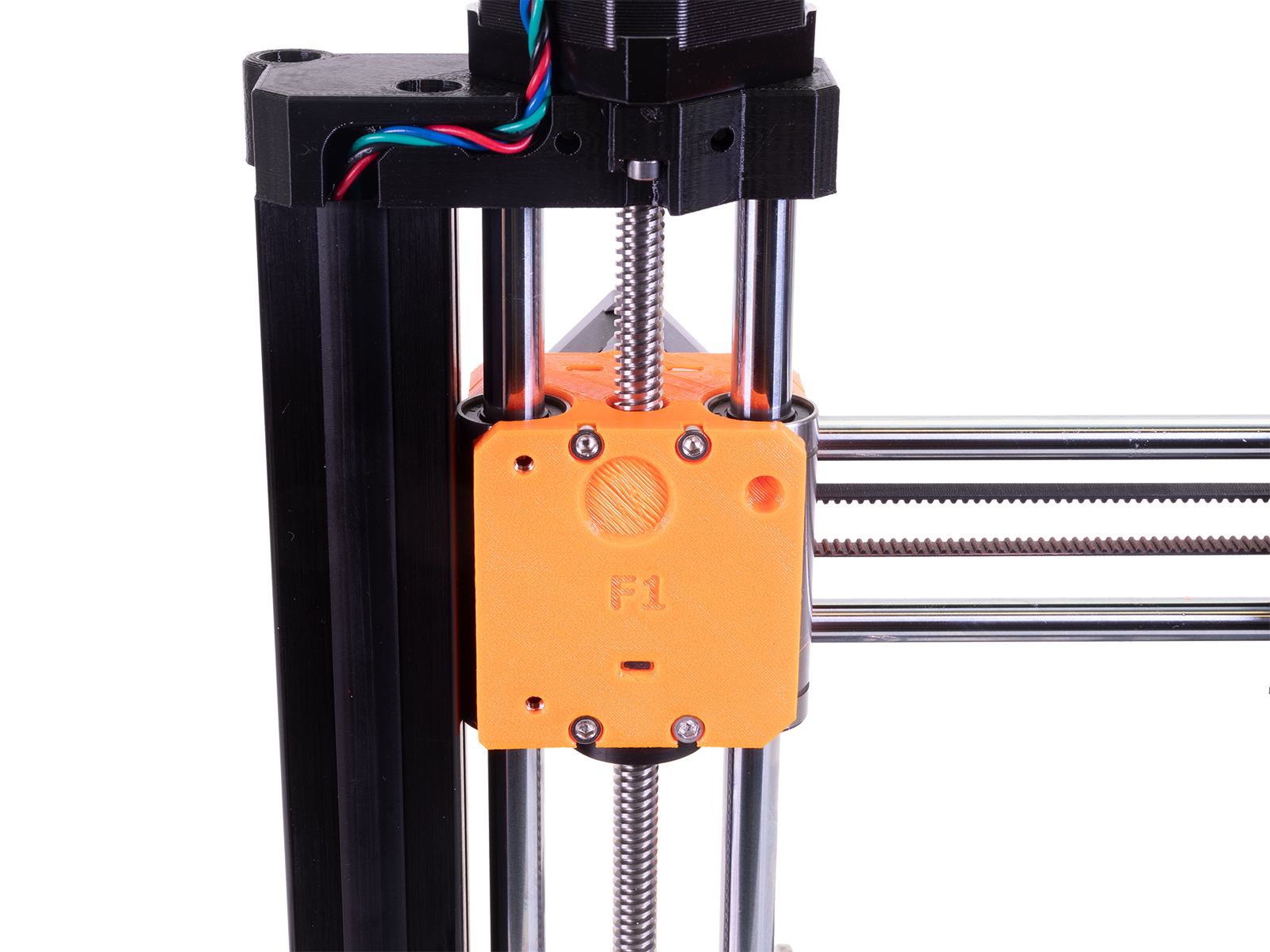 |
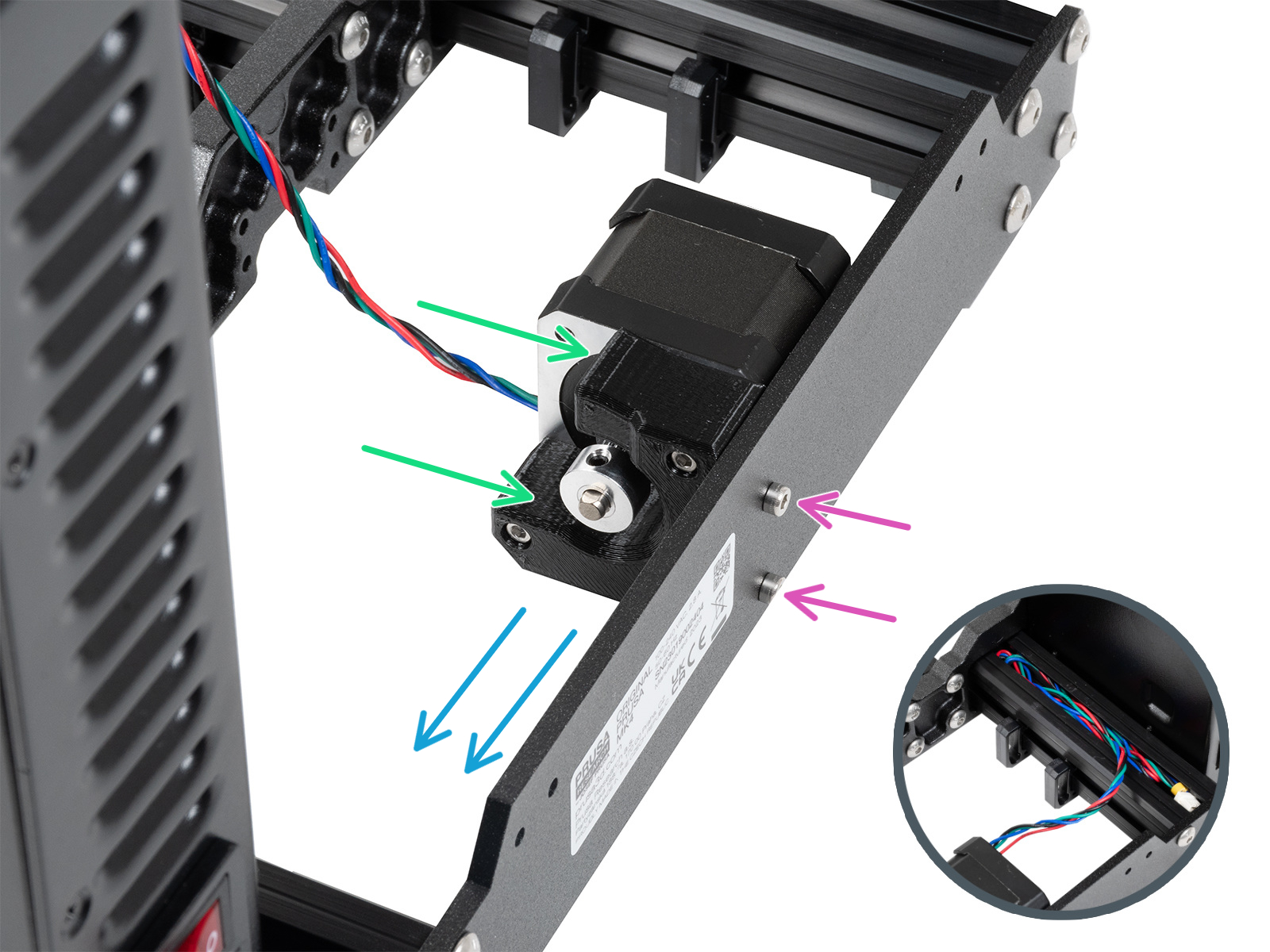
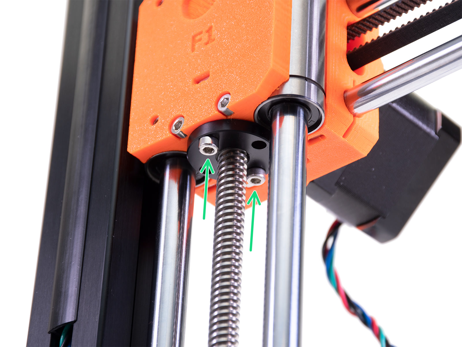
- Loosen the M3x20 screws holding the trapezoid nut.
- Hold the parts with your free hand! Loosen the M3x30 screws holding the X-axis block.

- Move the print head and look into the X-axis pulley inspection hole. Stop when you see a change in the inspection hole when one of the two pulley set screws is aligned with the hole.
- Compare the set screw position with the flat part of the motor shaft.

- In case of a loose or misaligned set screw, tighten one set screw against the flat part of the motor shaft, and ensure the second set screw is also reasonably tight. Use a 2.0mm Allen key for this step.
- Reassemble the printer by performing the above steps in reverse.