JA
  • English
  • Čeština
  • Español
  • Italiano
  • Deutsch
  • Polski
  • Français
Login

6B. Hinged lid with MMU2S

6B. Hinged lid with MMU2S
Relevant for:
Last updated a month ago
6B. Hinged lid with MMU2S
 Difficulty
Moderate
 Steps
24
 Available languages
ENCSPLDEESITFR
Introduction
Introduction
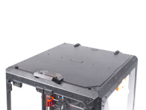
This chapter guides you through the installation of the MMU2S into the Enclosure.
The MMU2S can only be installed after the Hinged Lid is in place.
Removing the LCD
Removing the LCD
Removing the LCD
Removing the LCD
Carefully cut the zip tie securing the LCD cable bundle.
Release two screws mounting the LCD assembly.
Disconnect both LCD cables from the LCD.
Push the LCD cable bundle through the hole in the bottom panel into the enclosure.
Removing the filament guide
Press down the blue collet on the filament fitting.
Pull out the PTFE tube from the fitting.
Cut the zip tie securing the PTFE tube on the inner side of the top front profile.
Remove the two screws securing the filament guide and take it out of the enclosure.
Removing the printer
The following instructions show the MK3S+ with a black PSU, but the procedure is identical for the silver PSU.
Place the printer at an angle (as shown) inside the enclosure, positioning it behind the anti-slip dampers.
Unlock all PSU locks, then grasp the handle and remove the PSU assembly from the back panel.
Place the PSU on the heatbed, protected by a cloth, with the PSU handle facing upwards.
Removing the printer
Open the lid.
Grasp the printer by its frame and carefully lift it out of the enclosure.
Avoid scratching the printer and enclosure.
Installing the MMU2S
Now, proceed to the instructions for installing the MMU2S unit on the printer.
The procedure will vary slightly depending on whether the MMU2S unit was only temporarily removed from the printer during the enclosure assembly, or whether it was never installed on the printer at all. Choose your option:
Brand new installation of the MMU2S unit on the printer: go to Original Prusa i3 to MMU2S upgrade manual.
Re-mounting the MMU2S unit to the printer: go to  Assembling the MMU2S unit.
After you have finished installing the MMU2S unit on the printer, return to this guide and continue with the next step.
Preparing the printer (MK3S+ with MMU2S)
Before you place the printer in the enclosure, prepare the printer in this state:
LCD is disconnected and removed from the printer
PSU (both black and silver version) is removed from the frame and placed on the protected heatbed
The printer frame support is installed on the printer
Installing the printer
Grasp the printer by its frame and carefully insert it into the enclosure at a slight diagonal angle to avoid scratching the printer and enclosure.
Avoid placing the printer on cables and PTFE tubes!
Place the printer at an angle (as shown in the picture) in the enclosure behind the anti-slip dampers.
It's just a temporary position for the printer. We will adjust the correct position later.
Installing the PSU
Installing the PSU
Installing the PSU
Installing the PSU
From inside the enclosure, grasp the PSU by its handle in your hand.
It is more convenient to use the right hand.
Insert the PSU through the hole at the bottom of the back panel. Start by pushing through the part with the PSU-retainer (the part with the magnets).
Tilt the PSU towards the back panel, ensuring the PSU remains outside the enclosure while the PSU holder is inside the enclosure.
Ensure the PSU holder fits perfectly onto all four PSU locks.
Turn all PSU locks 90° to secure the PSU assembly.
Adjusting the printer
Rearrange position of the printer like in the picture. Place it in the center of the enclosure and adjust the correct position:
Ensure the two rear anti-slip dampers are locked against the rear plate from the inside.
The two front anti-slip dampers must be secured against the front plate from the outside.
Guide the LCD cable bundle under the printer, from the electronics to the front of the enclosure. Leave the cable loose for now.
Mounting the LCD
Mounting the LCD
Mounting the LCD
Mounting the LCD
Guide the LCD cable through the cutout in the bottom panel.
Secure the textile sleeve on the cable bundle with the zip tie. Do not over tighten the zip tie, it may cut the cables!
From the inside, push two M3x8 screws through the bottom profile.
Place the LCD assembly close to the LCD cables, like in the picture. Mind the same orientation of the LCD as in the picture. See the LCD-supports for better understanding.
Note that both cables are marked with stripes on one side. Correct connection order is important!
Connect the LCD cable marked with TWO STRIPES to the left slot (called EXP2) on the LCD controller.
Connect the LCD cable marked with ONE STRIPE to the right slot (called EXP1)  on the LCD controller.
Slide the LCD assembly onto the two M3x8 screws in the frame and tighten them.
Assembling the MMU-grommets
There are two symmetrical grommets for both edges of the enclosure's rearside. In case you intend to place all spools only on one side outside the enclosure, you can use just one grommet.
Using the Allen key, remove the print support from both MMU-grommets.
Insert the M3n nut into each MMU-grommet.
Mounting the MMU-grommets
Depending on where you will place your spools, cut out the left, right, or both sides.
From inside of the enclosure, use the knife and CAREFULLY cut off all supports of the left grommet cutout on the back panel and remove it.
From inside of the enclosure, use the knife and CAREFULLY cut off all supports of the right grommet cutout on the back panel and remove it.
Mounting the MMU-grommets
From inside, push the M3x8 screw through the hole next to the left grommet cutout.
From the outside, attach the MMU-grommet in the same orientation to the cutout and the screw. Tighten the screw.
Mounting the MMU-grommets (optional)
From inside, push the M3x8 screw through the hole next to the right grommet cutout.
From the outside, attach the MMU-grommet in the same orientation to the cutout and the screw. Tighten the screw.
Guiding the PTFE tubes
Merge all PTFE from the MMU2S and push them through the right MMU-grommet out of the enclosure.
You can use the left MMU-grommet as well. The procedure is the same.
Assembling the buffer feet
Release two screws securing the s-buffer-hook-uni and remove the printed part from the buffer.
Insert the screw into the nut in the s-buffer-hook-uni. Do not screw it completely, a few turn are enough.
Pull the screw and the nut out of the printed part. Take off the nut from the screw.
If it is difficult to pull the nut this way, take the spare M3n nut from the Enclosure kit package.
Do the same to extract the nut from the second s-buffer-hook-uni.
Insert the M3n nut into each MMU-buffer-foot.
Do not discard the screws, you will need them later again!
Mounting the buffer feet
Place and orient the buffer assembly as in the picture. Use the PTFE tubes as a guide.
Mount the MMU-buffer-foot on the right bottom edge of the buffer assembly.
Secure the MMU-buffer-foot with the M3x40 screw.
Mounting the buffer feet
Turn the buffer so that the mounted MMU-buffer-foot is on the left side.
Attach the second MMU-buffer-foot on the second bottom corner of the buffer assembly.
Secure the MMU-buffer-foot with the M3x40 screw.
Joining the buffer
Joining the buffer
Insert the PTFE from MMU2S unit to the buffer.
Secure the PTFE tube by tightening the M3x12 screws. Don't over-tighten the screw. Excessive friction in the PTFE might cause issues during the printing later.
他のすべてのPTFEチューブに同じことを繰り返します。フィラメントの位置はお好みで整理してください。
That's it!
That's it!
That's it!
Arrange the buffer and filaments.
As an example, you can use the arrangement tested by us, which you can see in the picture.
Was this guide helpful?

Comments

Still have questions?

Still have questions?

If you have a question about something that isn't covered here, check out our additional resources.
And if that doesn't do the trick, you can send an inquiry to [email protected] or through the button below.

Contact us