日本語
Login
3Dプリンター
マテリアル
部品 & アクセサリー
法人向け
ソフトウェア
3Dモデル
コミュニティ
ヘルプ
コース一覧
ブログ
会社概要
サポート
Original Prusa MINI
Original Prusa MINI Enclosure (1.0)
3. Installing the printer | Tools necessary for this chapter
1. Tools necessary for this chapter
ステップ 1 / 20 (章 3 / 4)
内容
コメント
⬢
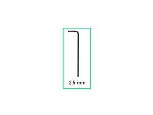
For this chapter, please prepare:
⬢
2.5mm Allen key
Loading...
次
内容
Original Prusa MINI Enclosure
1. はじめに
2. Assembling the Enclosure
3. Installing the printer [進行中の翻訳]
Tools necessary for this chapter
Removing the input PTFE tube (optional)
Removing the filament sensor (optional)
Input PTFE tube: parts preparation (optional)
PTFEチューブを挿入する
フィラメントセンサーの取り付け (オプション)
Preparing the printer
Installing the printer
Connecting the PSUs: parts preparation (add-on)
Connecting the PSUs (add-on)
Connecting the cables
Adjusting printer position
Thermometer: parts preparation
Assembling the thermometer
Spool holder: parts preparation
Installing spool holder
Mounting the side arm
Sticking the label
Haribo time!
That's it
Manual changelog MINI Enclosure
コメント
ログイン
してコメントを投稿する
コメントなし