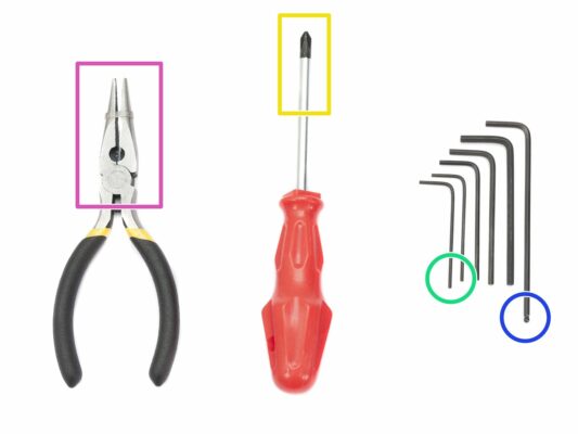
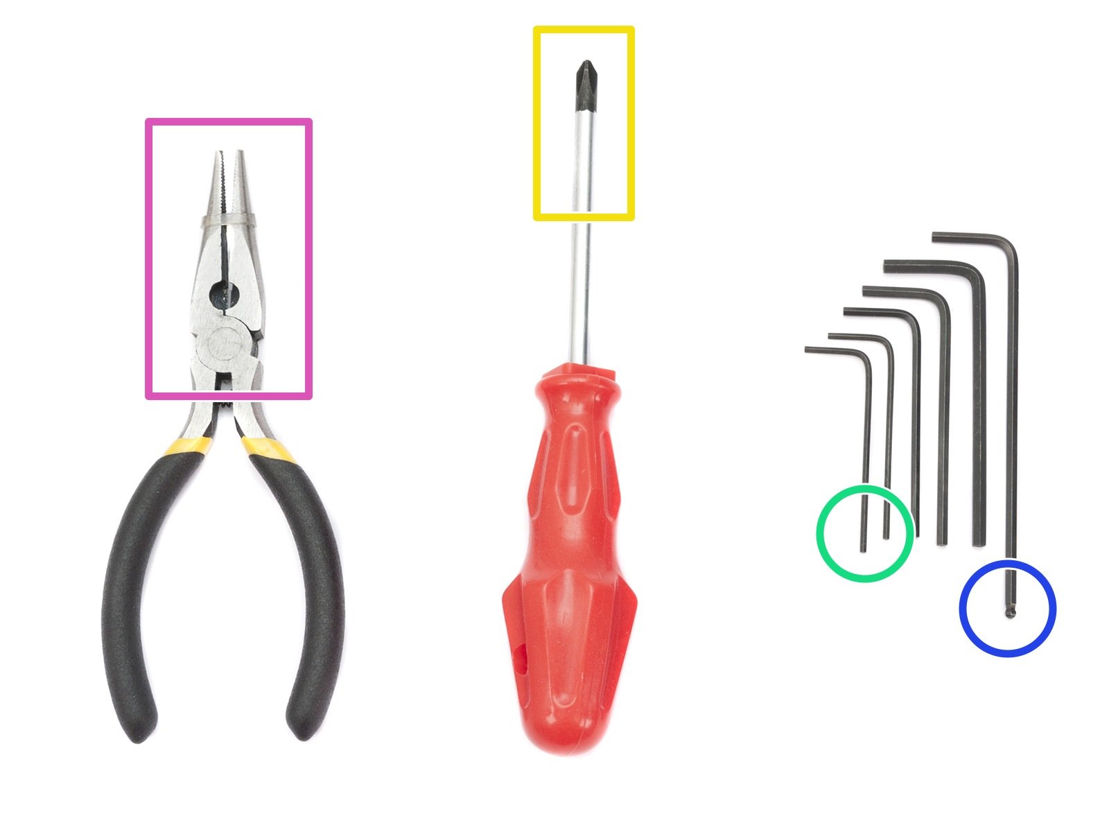
⬢Needle-nose pliers for zip tie trimming.
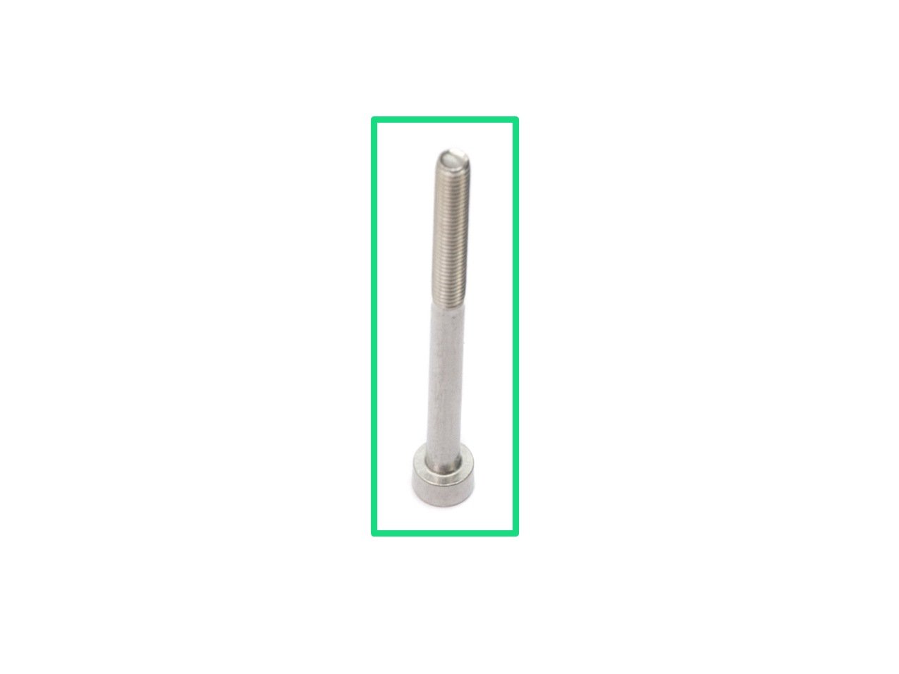
⬢2.5mm Allen key for M3 screws
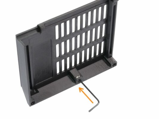
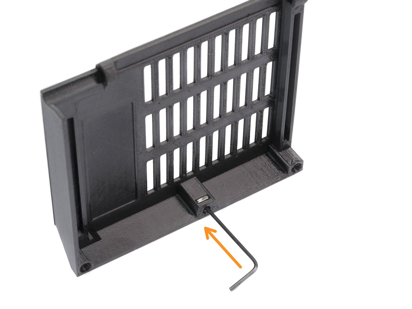
⬢1.5mm Allen key for nut alignment
⬢Philips screwdriver to tighten PSU and HB cables


If you have a question about something that isn't covered here, check out our additional resources.
And if that doesn't do the trick, you can send an inquiry to [email protected] or through the button below.

