EN
  • Čeština
  • Español
  • Italiano
  • Deutsch
  • Polski
  • Français
  • 日本語
Login

5. E-axis assembly (textile sleeve)

Menu

5. E-axis assembly (textile sleeve)

5. E-axis assembly (textile sleeve)
Relevant for:
Last updated a year ago
5. E-axis assembly (textile sleeve)
 Difficulty
Difficult
 Steps
50
 Available languages
CSPLESDEITFRJA
Textile sleeve vs spiral wrap
Before you proceed further ensure again, you are in the correct chapter:
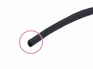
The longest and biggest sleeve is a textile sleeve. If so, you can proceed according to this chapter.
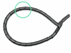
If the longest and biggest sleeve is a spiral wrap, please use this chapter instead: 5. E-axis assembly (spiral wrap)
Tools necessary for this chapter
Needle-nose pliers for zip tie trimming.
2.5mm Allen key for M3 screws
2mm Allen key for nut alignment
1.5mm Allen key for tightening the pulley
Idler assembly (part 1)
For the following steps, please prepare:
Extruder-idler (1x)
Bondtech pulley WITHOUT the hole for the lock screw (1x)
Pulley bearing (2x)
M3nS nut (2x)
Pulley shaft (1x)
Note there are two types of the Bondtech pulley in the package (one with hole and without hole for the lock screw). Make sure you are using the correct one.
Idler assembly (part 2)
Press the nuts to the slots on both sides of the idler.
Insert both bearings in the pulley. Be aware that bearings can slip out during assembly.
Layers might be visible in this printed part due to the geometry. The functionality and strength remain unaffected.
Idler assembly (part 3)
Ensure both bearings are inside the pulley!
Insert the pulley in idler as shown in the picture.
Slide the shaft through the idler and pulley. Use reasonable force or you will BREAK the printed part.
Place your finger on the bearing and ensure it can rotate freely.
Assembling filament sensor (part 1)
BE CAREFUL with the filament sensor, do not touch the black PCB nor the chips on it.
For the following steps, please prepare:
Extruder-body (1x)
Filament sensor (1x)
The filament sensor is in the box labeled "2.3.4.5 SUP".
M3x10 screw (1x)
M3n nut (2x)
Assembling filament sensor (part 2)
Before we continue with the assembly, we need to insert nuts in the Extruder-body. Take the extra time and effort to place them in properly. You won't be able to reach them later.
Rotate the front part towards you and insert the M3 nut in the slot, all the way in.
Rotate the rear part towards you and insert the M3 nut in the slot, all the way in.
If you can't push the nuts in, use a longer screw from the other side and tighten it until you "pull" the nut in.
Assembling filament sensor (part 4)
Turn the extruder-body like in the picture. The pins of the filament sensor must be facing up.
Locate the opening for the M3 screw.
Take the M3x10 screw and tighten the sensor in place. No nut is needed, the screw will self-tap into the plastic.
The sensor must be tightened completely to prevent its movement (screw head touching the board) BUT BE CAREFUL during tightening to avoid damage to the sensor.
Layers might be visible in this printed part due to the geometry. The functionality and strength remain unaffected.
Extruder assembly - idler (part 1)
For the following steps, please prepare:
M3x30 screw (1x)
M3 translucent washer (2x)
Translucent washers are placed on the idler for better visibility. No need to place them as in the picture ;)
Extruder assembly - idler (part 2)
Turn the Extruder-body like in the picture. The pins must be facing to the right.
Insert M3x30 screw in the hole.
Place a washer from the other side.
Assemble the idler on the M3x30 screw.
Finish the assembly with the second washer.
If the second washer keeps falling off. Use a M3n nut from the spare bag to fix it temporarily.
Assembling the Extruder motor pulley (part 1)
For the following step, please prepare:
Extruder motor (1x)
Bondtech pulley WITH the hole for the lock screw (1x)
In case the lock screw is sent separately, screw it in the pulley slightly. Ensure the tip of the lock screw isn't reaching to the internal part of the pulley as it might block the shaft in the next step.
Ensure you are using the correct motor, there is a label on the bottom of the casing. The reason is, each motor has different cable length.
There is a second spare lock screw in the package.
Assembling the Extruder motor pulley (part 2)
There is a flat part on the motor shaft, rotate it towards you.
Slide the pulley on, note the CORRECT orientation.
The screw must be facing directly against the pad (flat part) on the shaft. Slightly tighten the screw, the final adjustment will be done later.
Don't press the pulley against the motor. Leave it on the very top of the shaft, see the picture.
Before moving to the next step, rotate the pulley 90-degrees clockwise ( the lockscrew will be facing to the left).
Mounting the Extruder motor
Find in the package two M3x30 screws and insert them into the holes.
Before mounting the motor, ensure the second translucent washer is still on the top M3x30 screw.
Mount the motor on the extruder body as shown in the picture, double check the proper orientation of the motor cables.
Tighten both screws firmly.
Tighten the screw, but only slightly, keep in mind the idler must rotate freely.
Adjusting and tightening the pulley
Open idler fully to have direct access to the pulley.
Use a piece of 1.75 mm filament (from the spool) to align the pulley with the openings for the filament (see the picture). Arrows only indicate the direction. Don't use the 3mm nylon filament!
Adjust the pulley and tighten it with 1.5mm Allen key. Use reasonable force as you might damage the thread.
Once the pulley is perfectly aligned, please remove the filament.
Securing the Extruder idler
For the following step, please prepare:
M3x40 screw (2x)
Extruder spring (2x)
Assemble springs on both screws, see the second picture.
Close the idler, so the screws can reach it.
Place both screws into the Extruder body (see the picture) and tighten them. The screw's head should be almost aligned with the printed surface.
E3D V6 hotend - different versions
In the kit you can find two versions of the hotend:
E3D V6 hotend with regular PTFE tube (old version, no marking)
E3D V6 hotend with MMU2 PTFE tube (newer version, marked with a green dot)
Both versions are perfectly fine for a single material MK3. The newer version is optimized for customers planning to upgrade to the MMU2 (with the previous "regular" version, you have to change the PTFE yourself).
DON'T REMOVE the PTFE tube, it has to be in the hotend.
Inserting the E3D hotend
Take the E3D hotend and place it inclined into the Extruder body. Make sure the white PTFE tube fits in properly.
Insert the hotend into the Extruder body, see the picture.
Make sure the hotend is fully seated and the upper part aligned (almost in contact) with the surface of the printed part.
Note the CORRECT orientation of the hotend.
Be VERY CAREFUL with the hotend wires from now on, you can damage them.
Mounting the extruder-cover
Rotate the extruder as shown in the first picture.
Take the extruder-cover and place it on the extruder body. Both printed parts must be in direct contact.
Using M3x25 screws tighten both parts together. If you can't reach the nuts, use temporarily a longer screw from the spare bag (e.g. M3x30).
Ensure again the hotend is properly assembled. The surface of the heatsink (part of the hotend with cooling ribs) must be aligned with the surface of the printed parts. See the last picture.
Preparing cooling fans
For the following steps, please prepare:
M3x18 screw (4x)
Left hotend fan (1x)
Front print fan (1x)
The left hotend fan has two sides, but the side with sticker must be always facing the hotend (not visible when the fan is mounted). Otherwise, the cooling won't work properly.
The left hotend fan (Noctua) can be also in a black colour without the rubber corners, other hardware parameters are the same.
Mounting the left hotend fan
Place the Extruder on the side and guide the wires from the motor in the slot.
Place the Left hotend fan on the Extruder. The cable must be placed in the top left corner, see the picture.
Note the correct orientation of the fan. The sticker has to face towards the hotend!
Insert M3x18 screws and tighten them slightly.
Now, tighten ALL screws, alternating diagonals. After tightening, check that the fan can still rotate freely.
DON'T tighten the screws too hard, all parts are made of plastic and you can break them.
Mounting the front print fan - parts B7/R3
For the following steps, please prepare:
nozzle-fan-45deg-support (1x)
nozzle-fan-45deg (1x)
M3x18 screw (1x)
M3x10 screw (2x)
M3n nut (1x)
In case you are missing one M3x10 screw please use the spare bag.
Mounting the front print fan - parts B7/R3
Press the M3n nut in the support, all the way in. It will be barely visible. If needed use a screw from the other side to pull the nut in, then remove the screw.
WARNING: there are pins of the filament sensor on the other side of the extruder. Be careful as you might bend them during the following steps!!!
Connect the support to the extruder using the M3x10 screw. Note the correct orientation in the picture.
The inclined part of the support must be facing to the extruder cover.
Place the nozzle-fan on the extruder and secure it using M3x10 screw.
Preparing the P.I.N.D.A. probe
For the following steps, please prepare:
P.I.N.D.A. sensor (1x)
M3x10 screw (1x)
M3nS nut (1x)
The probe is a sensitive device, please handle it with care during the assembly!
The P.I.N.D.A. cable can be either black or grey, both probes are the same.
Make sure there are FOUR wires in the connector, if not, please stop the assembly and contact our support asap.
Mounting the P.I.N.D.A. probe
Start with the front print fan wire and place it under the cable clip.
Gently push the P.I.N.D.A. sensor through the holder. If the hole for the sensor is too tight, you can open it slightly, but be very careful as you might break it!
Create a loop on the probe wire, then place the wire under the cable clip.
Slide the M3nS nut in the slot and tighten the probe SLIGHTLY with the M3x10 screw.
The exact position of the P.I.N.D.A. probe will be adjusted later (in Chapter 9, Preflight check), so there is no need to adjust the probe or tighten the screw fully at this point.
Extruder cables preparation
Place the Extruder on the Y-carriage as in the first picture. Ensure the correct orientation of the printer, shorter extrusions must be facing towards you.
If needed, lower the X-axis so you can see the entire X-carriage. It is needed for the next step.
Take the cables from P.I.N.D.A. probe and front print fan, slide it between the lower smooth rod and belt.
Take the cables from Extruder motor and left hotend fan, slide it between the lower smooth rod and belt.
IT IS VERY IMPORTANT to place the cables as shown in the pictures. Please double check your steps.
Cables from hotend will be placed under the lowest smooth rod. We will arrange them later.
Mounting the Extruder
For the following step, please prepare:
M3x40 screw (1x)
M3x30 screw (1x)
M3x18 screw (1x)
Place the Extruder near the X-carriage and check no wire is pinched. There is a slot in the X-carriage for the motor wires, see the picture. Bend the motor cable in it and leave the fan wires straight.
Mount the Extruder on the X-carriage using the screws above. Tighten all screws, but not fully. We need to arrange the cables again, this time in the back.
Guide the cables through slots (channels) on both sides of the Extruder. On the left side, it is Front Print fan and P.I.N.D.A. probe, on the right side Extruder motor and Left Hotend fan.
Ensure again the cables are pushed to the channels (not sticking out) and not pinched between printed parts. Now, tighten all screws, equally to prevent issues.
Cable for the filament sensor
Locate the cable for filament sensor in the package.
There are two types of the connectors on the cable:
The 4-pin connector for the sensor (used now)
The 5-pin connector for the EINSY board (used later)
Connecting the Filament sensor
Use the cable from the previous step and connect it carefully to the filament sensor.
Note the connector has two different sides. The side with safety pin must be on the left (white wire is facing up and red down).
Gently rotate the cable (clockwise) to create a small loop, see the second picture.
Push the cable through the opening on the X-carriage.
Preparing the NYLON filament
Starting mid of February 2018, there will be only one 50cm NYLON filament included.
There are two NYLON filaments included in the kit with lengths 50 and 30 cm. Both have Ø 3 mm. For this step please use the longer one and DON'T TRIM any of them!
Using the pliers cut one end of the filament to create a tip.
Check the tip is similar to the third picture.
Inserting the NYLON filament
Locate the hole for the NYLON filament. Using the smallest Allen key ensure there are no obstacles inside.
Using the pliers insert and twist the NYLON filament in the slot. Hold the extruder with your second hand.
BE EXTREMELY CAREFUL as the pliers tend to slide and you can easily damage the wires!!!
To check if the filament is seated properly, gently pull it with your hand. The X-axis should bend a little, but the filament must remain in the slot.
If you have issues, try to adjust the tip on the filament.
Preparing the X-carriage-back (part 1)
For the following steps, please prepare:
X-carriage-back (1x)
Cable-holder (1x)
M3n nut (1x)
M3x10 screw (1x)
The M3x10 screw will be used temporarily, use one from the spare bag.
M3x40 screw (1x)
Preparing the X-carriage-back (part 2)
Insert the M3x10 screw in the X-carriage-back. Tighten it completely.
Rotate the printed part and insert the M3n nut.
Tighten the M3x10 screw until the nut slides in the printed part. Note the shape of the cutout for the nut, you might need to adjust (rotate) the nut.
Remove the M3x10 screw and place it back in the spare bag.
Preparing the X-carriage-back (part 3)
Prepare the M3x40 screw and cable-holder from the previous step.
Tighten the screw all the way through the printed part.
Note there is a recess (slot) for the screw's head on one side of the printed part.
Preparing the X-carriage-back (part 4)
Place the X-carriage-back as in the picture. You must see the MK3 sign.
Tighten the X-carriage-back and the cable-holder together.
Check the "u-shaped" slot is aligned properly on both parts.
Assembling the X-carriage-back
Push the cables from the Extruder THROUGH the X-carriage-back. Start with Extruder motor and the Left hotend fan.
In the next step add the Front print fan and P.I.N.D.A. probe cables.
Cables from hotend and filament sensor are NOT GOING through the X-carriage-back!
Carefully insert the nylon filament and then slide the X-carriage-back towards the X-axis.
Adjusting the filament sensor cable
Before pressing the X-carriage-back against the X-axis, place the filament sensor cable through the slot. See both pictures.
Check the cables are not pinched between the X-carriage-back and the X-axis!!!
Mounting the X-carriage-back
Using five M3x10 screws tighten the parts together in following order:
Start in the middle and ensure proper alignment.
Continue in the corners, tighten all screws equally.
After the tightening is done, push the filament sensor cable in the slot along X-carriage-back, join the remaining cables.
Tightening the textile sleeve (part 1)
For the following steps, please prepare:
Zip tie (5x)
Textile sleeve 13 x 490 mm (1x)
There are three textile sleeves in the package, use the largest one (both diameter and length).
Tightening the textile sleeve (part 2)
Open one end of the textile sleeve and slide it on the cable bundle leading from the extruder. Don't forget to include the nylon!
Leave the cables from the Hotend out for now.
Length of the first wrap should be slightly longer than the cable-holder part, about 5 cm is enough.
Gently twist the sleeve to make it smaller and tighter around the cables and slide the sleeve towards the extruder.
Take 3 zip ties and insert them into the lower row of holes on the cable-holder.
Twist the sleeve again (without twisting the cables inside) and tighten the zip ties.
IMPORTANT: Cut the remaining part of each zip tie using pliers as closest to its head as possible. Note the correct position of each zip ties's head (slightly off-centre to the left).
Tightening the textile sleeve (part 3)
Use two zip ties and push them through the upper slots on the cable-holder.
ATTENTION! Before tightening the zip ties add the cables from the hotend.
Once the hotend cables are included, tighten the zip ties and cut remaining parts.
Open the textile sleeve and insert the cables from the hotend.
Compare the look of the cable management with the last picture.
Mounting the Filament-sensor-cover (part 1)
For the following steps, please prepare:
Idler-plug (1x)
Filament-sensor-cover (1x)
PTFE tube 4x2x13 mm (1x)
M3x10 screw (2x)
In case you are missing one M3x10 screw please use the spare bag.
Mounting the Filament-sensor-cover (part 2)
Insert the short PTFE in the printed part from below. Orientation of the tube doesn't matter, both ends are the same.
Locate the largest circular opening for the PTFE tube on the top of the Extruder.
Assembling the idler-plug
Locate the part, where the idler is cut out (M3 screw is visible).
Insert the idler-plug and ensure it fits properly. Otherwise, it might fall down during the print.
E-axis is finished!
E-axis is finished!
Are we there yet? Almost! You've just finished the hardest part of the assembly. Awesome job!
Check the final look, compare it to the picture. Note with B7/R3 parts the extruder looks different.
Checked everything? Let's move to: 6. LCD assembly
Was this guide helpful?

Comments

Still have questions?

Still have questions?

If you have a question about something that isn't covered here, check out our additional resources.
And if that doesn't do the trick, you can send an inquiry to [email protected] or through the button below.

Contact us