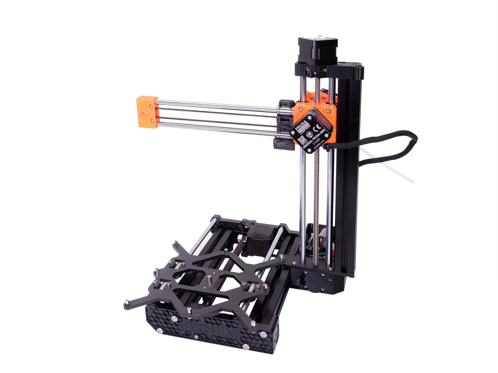
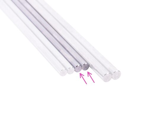
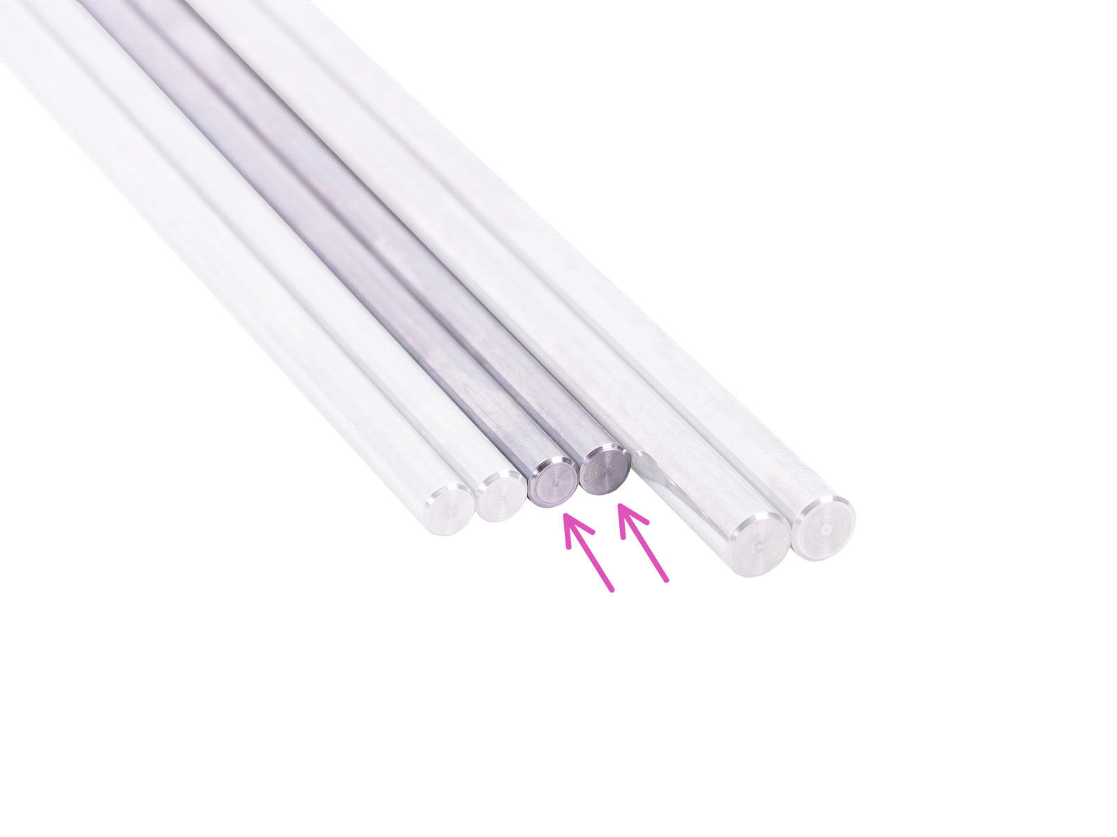
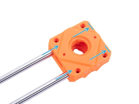
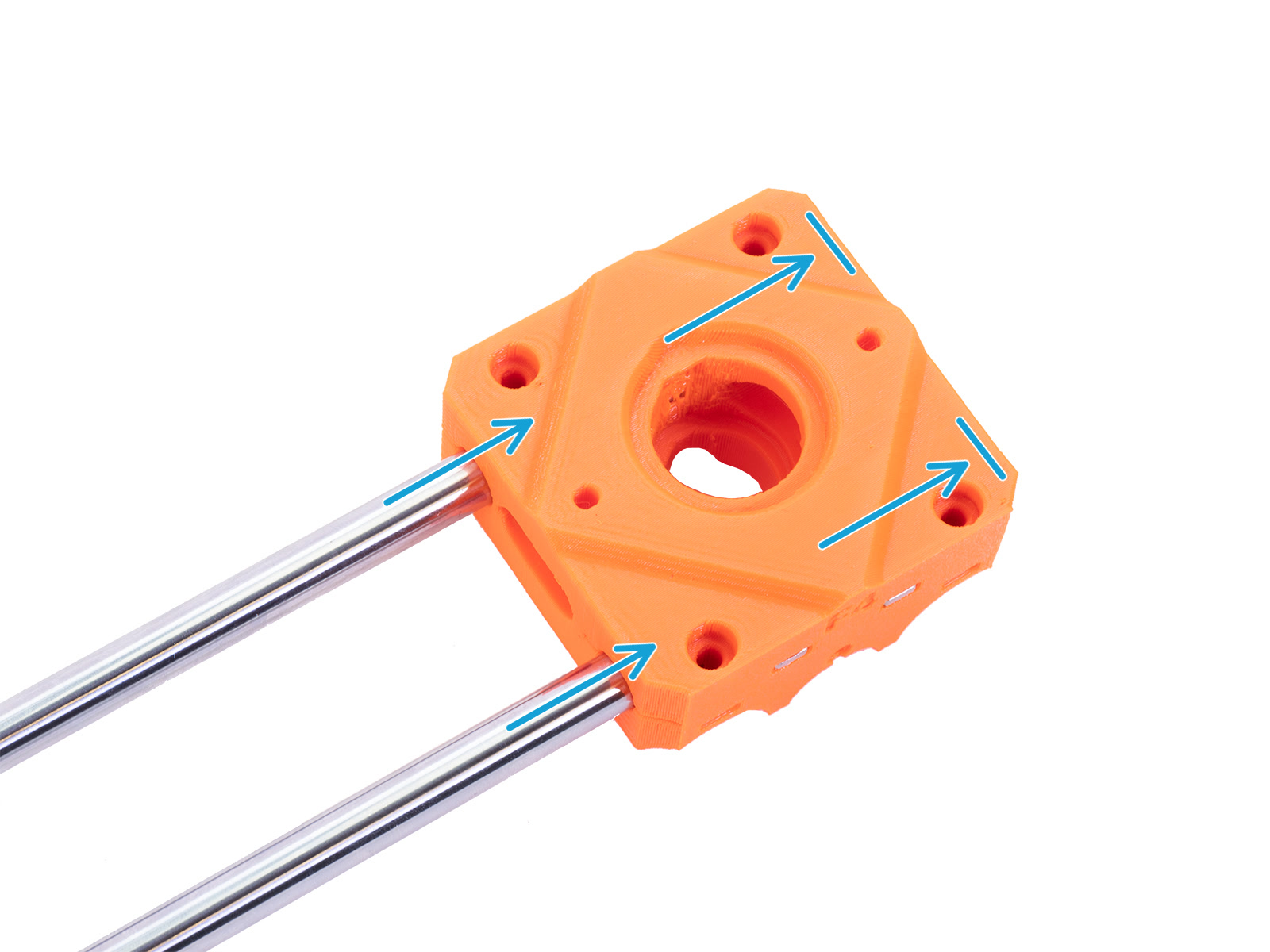
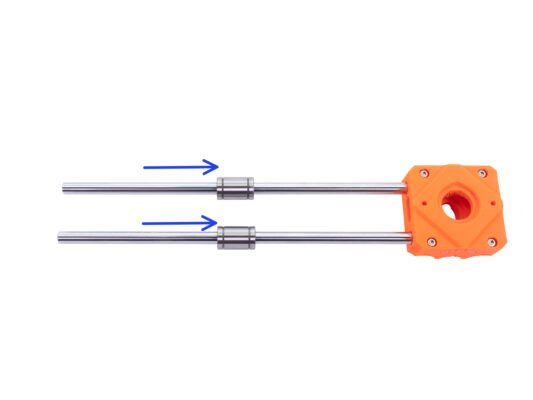
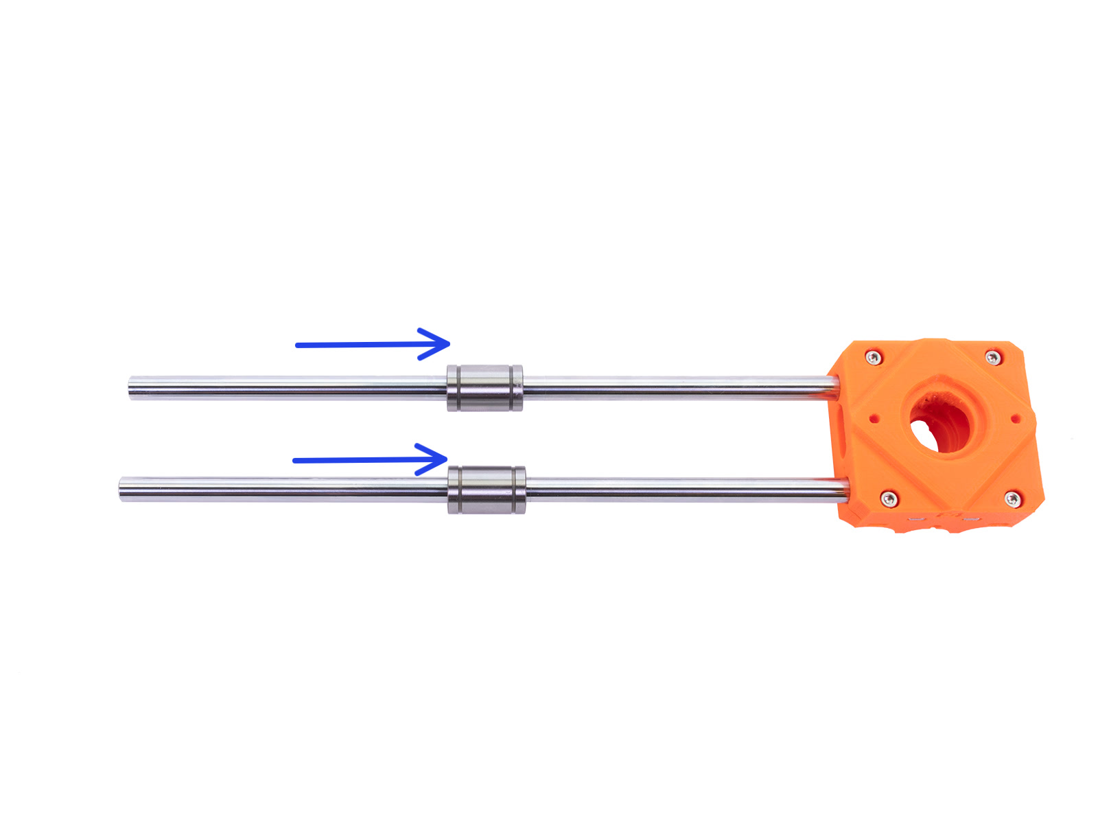
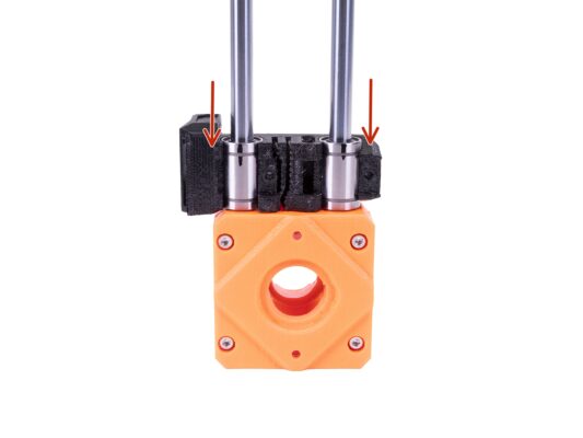
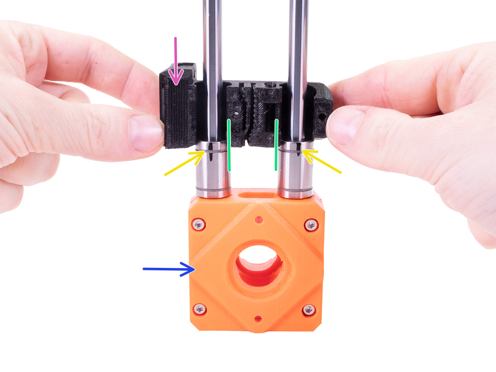
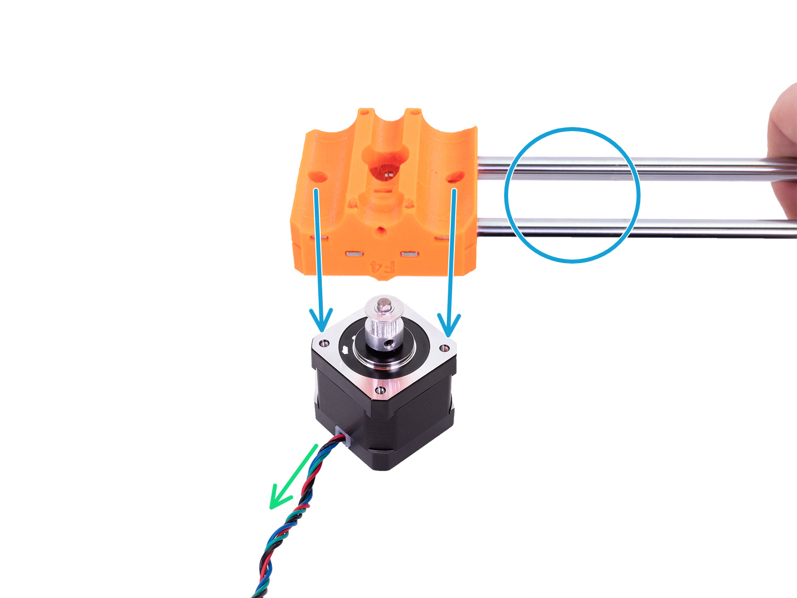
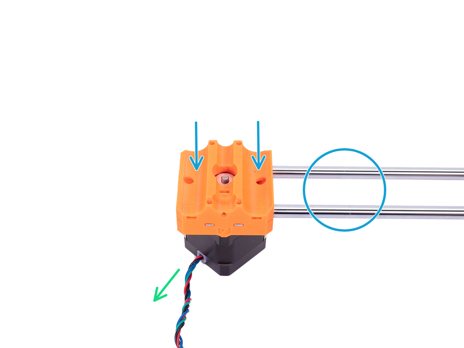
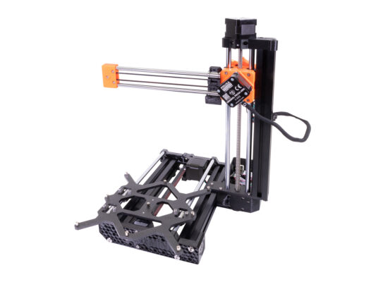
⬢Carefully slide both smooth rods all the way into the MINI-Z-carriage-front. Before inserting the smooth rods, check if there are no obstructions inside the holes.
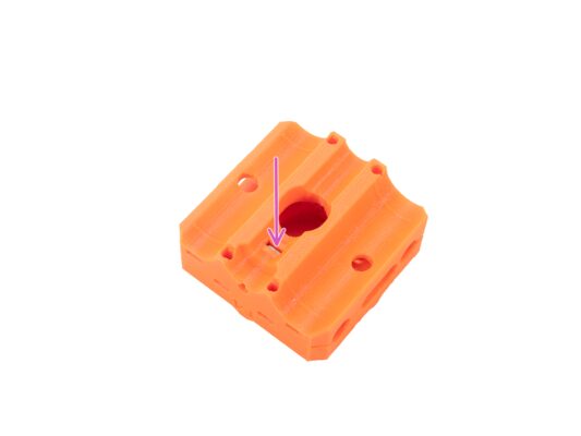
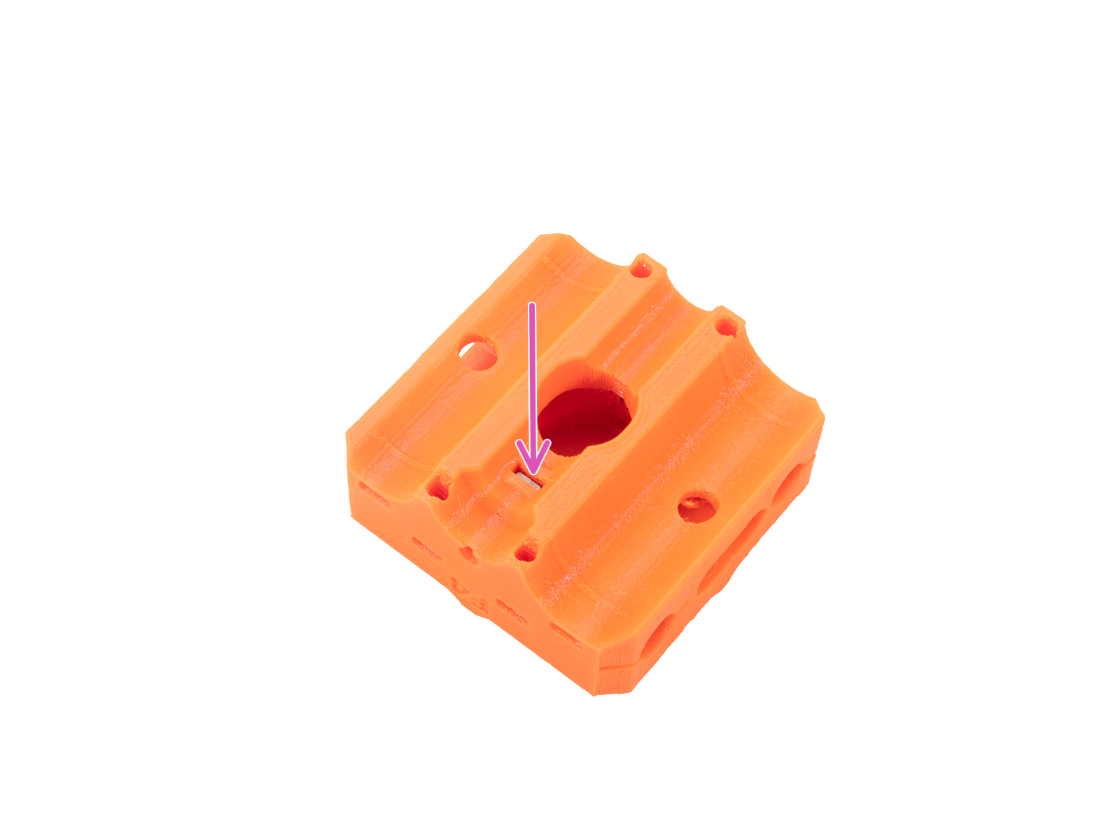
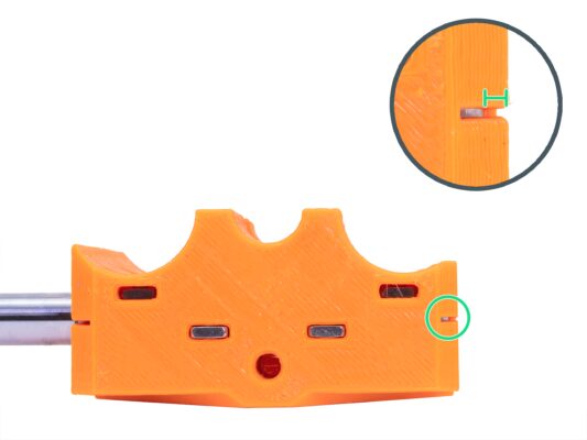
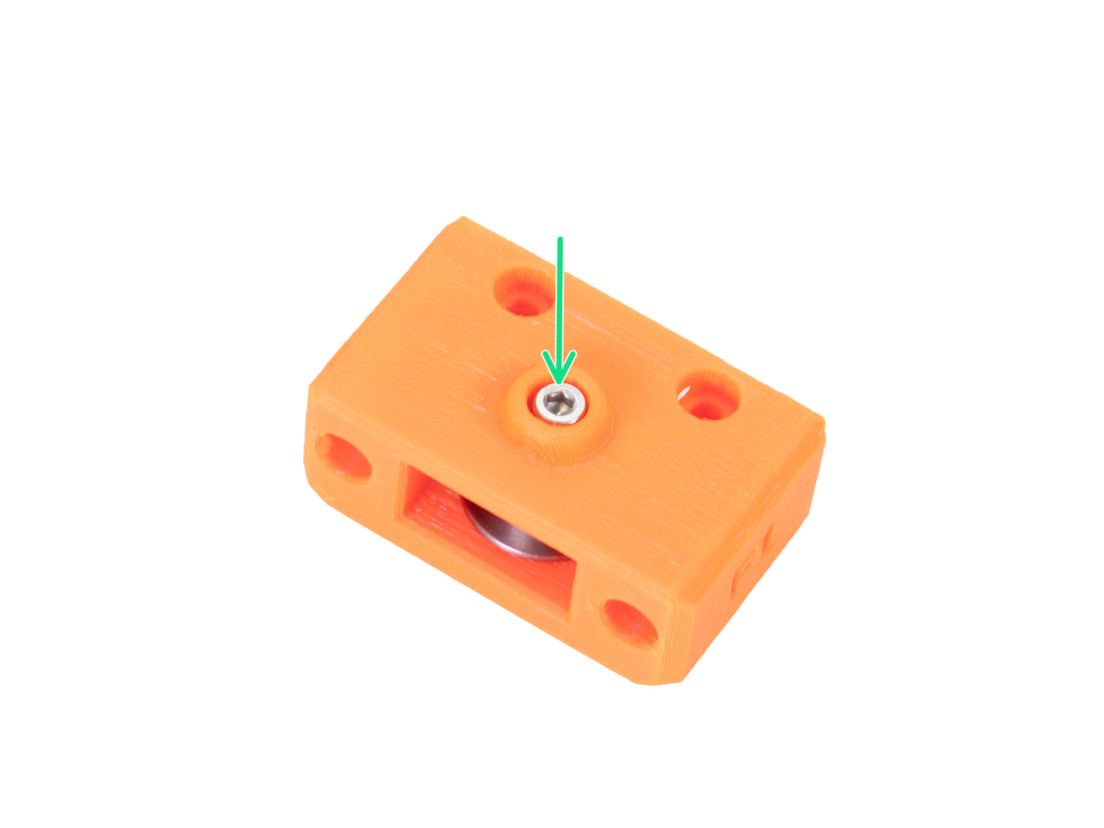
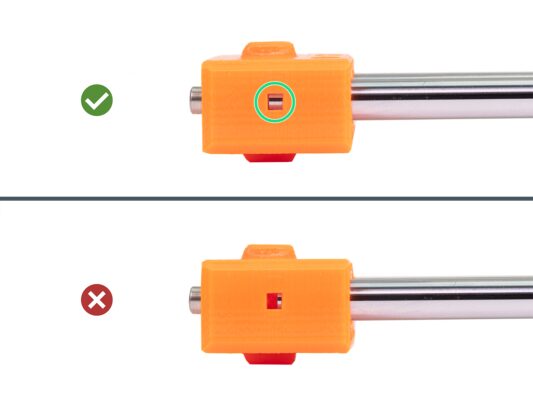
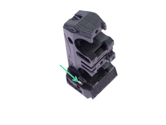
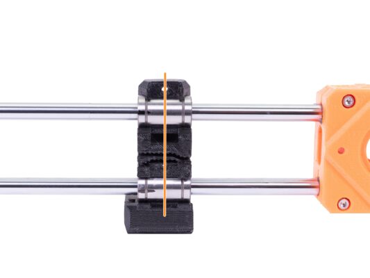
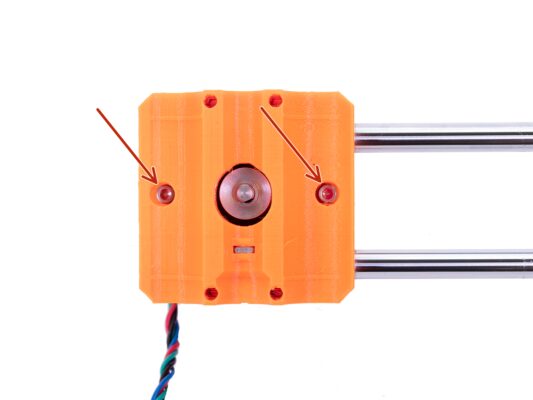
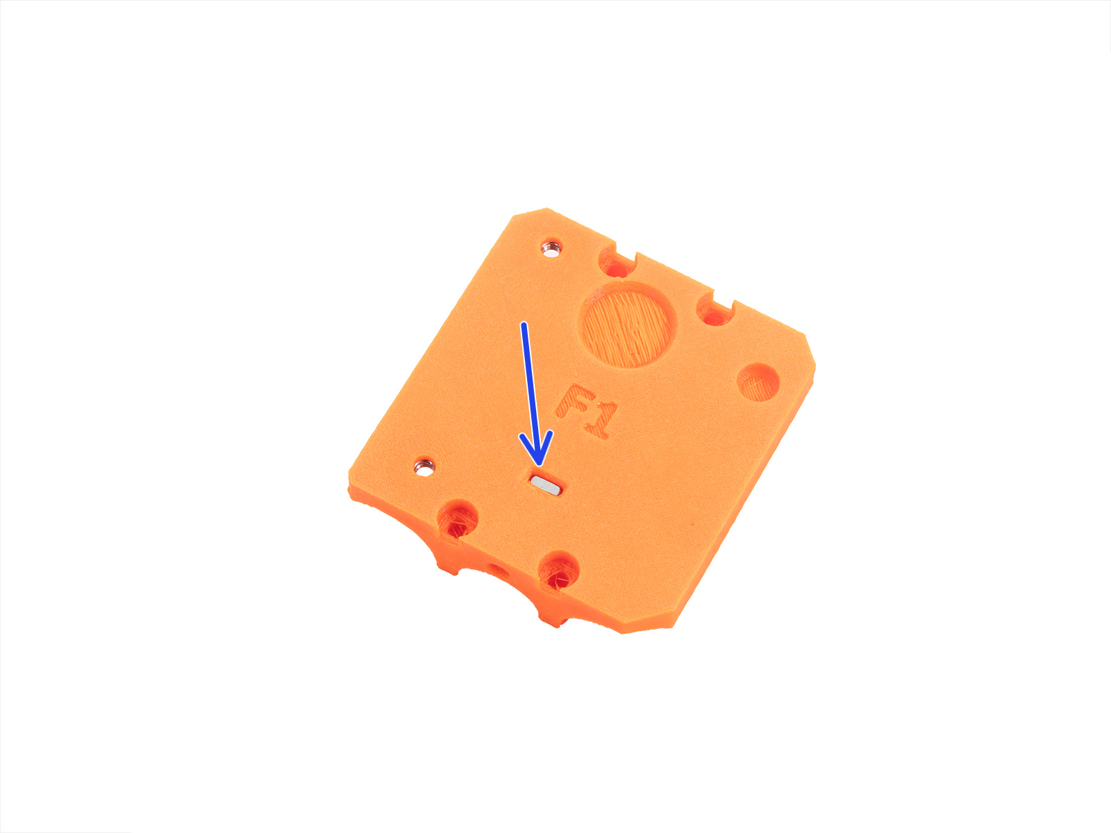
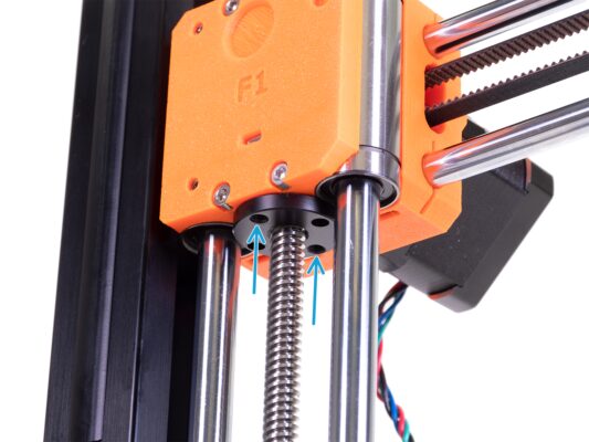
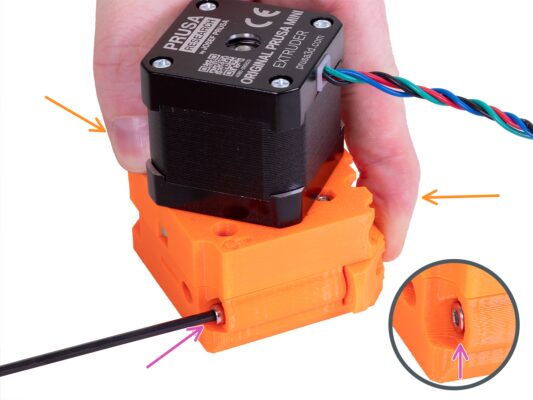
⬢Look sideways on the MINI-Z-carriage-front through the inspection hole and check that the smooth rod is fully inserted into the plastic part.
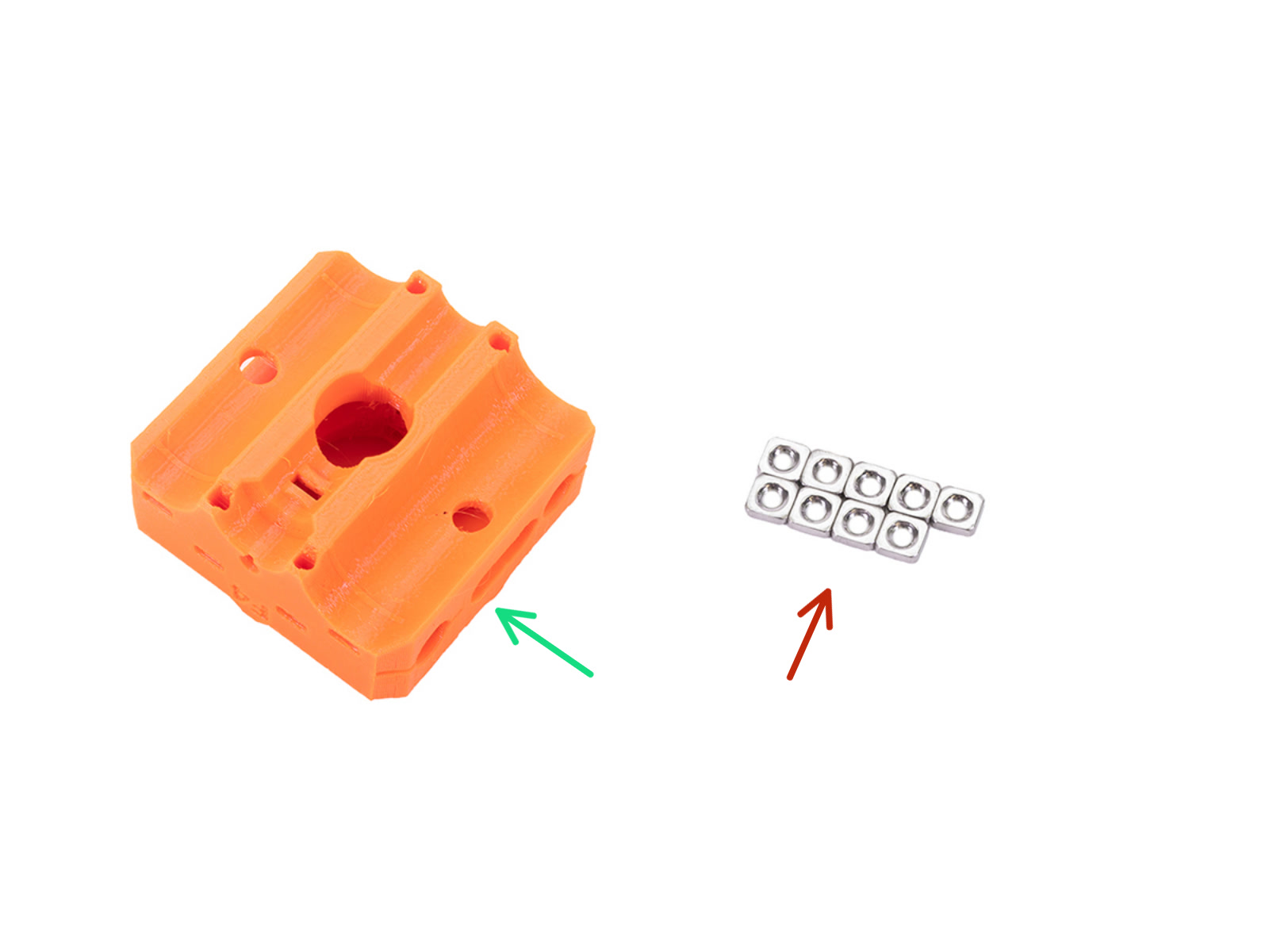
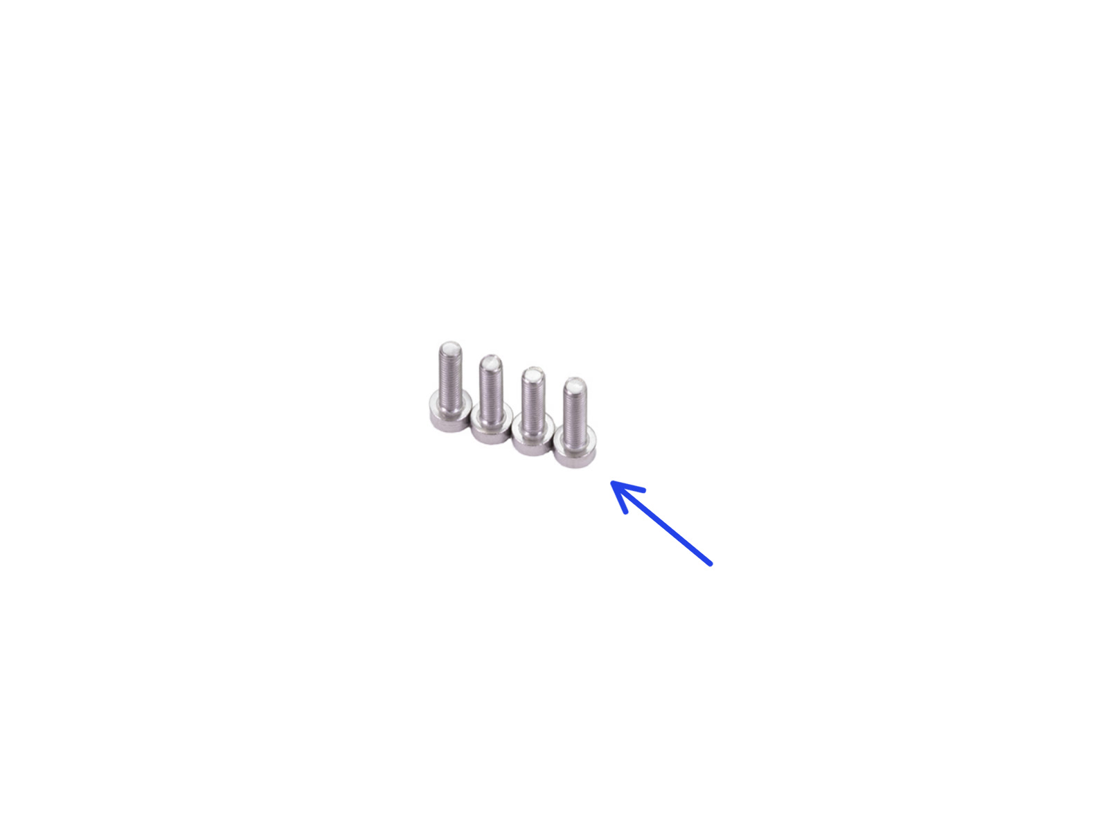
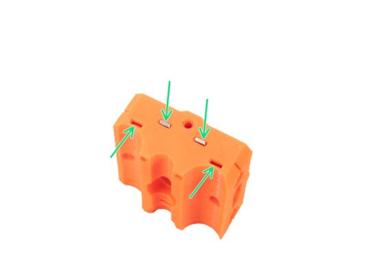
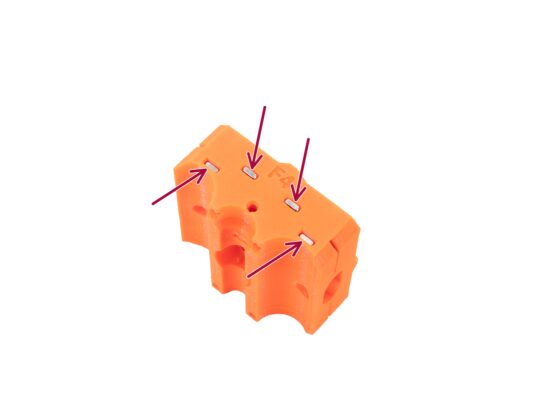
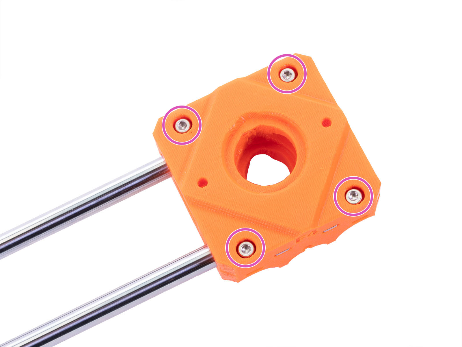
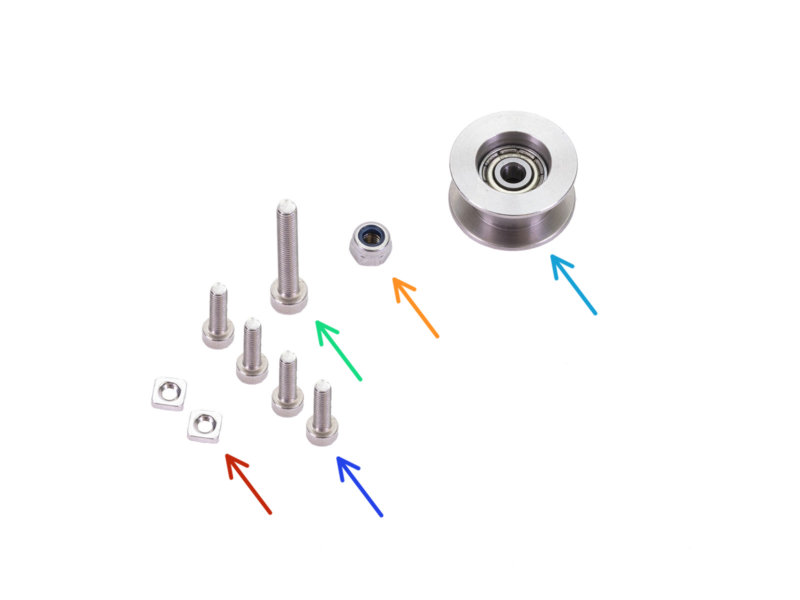
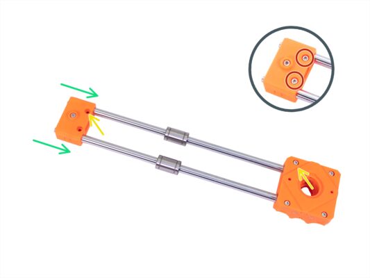
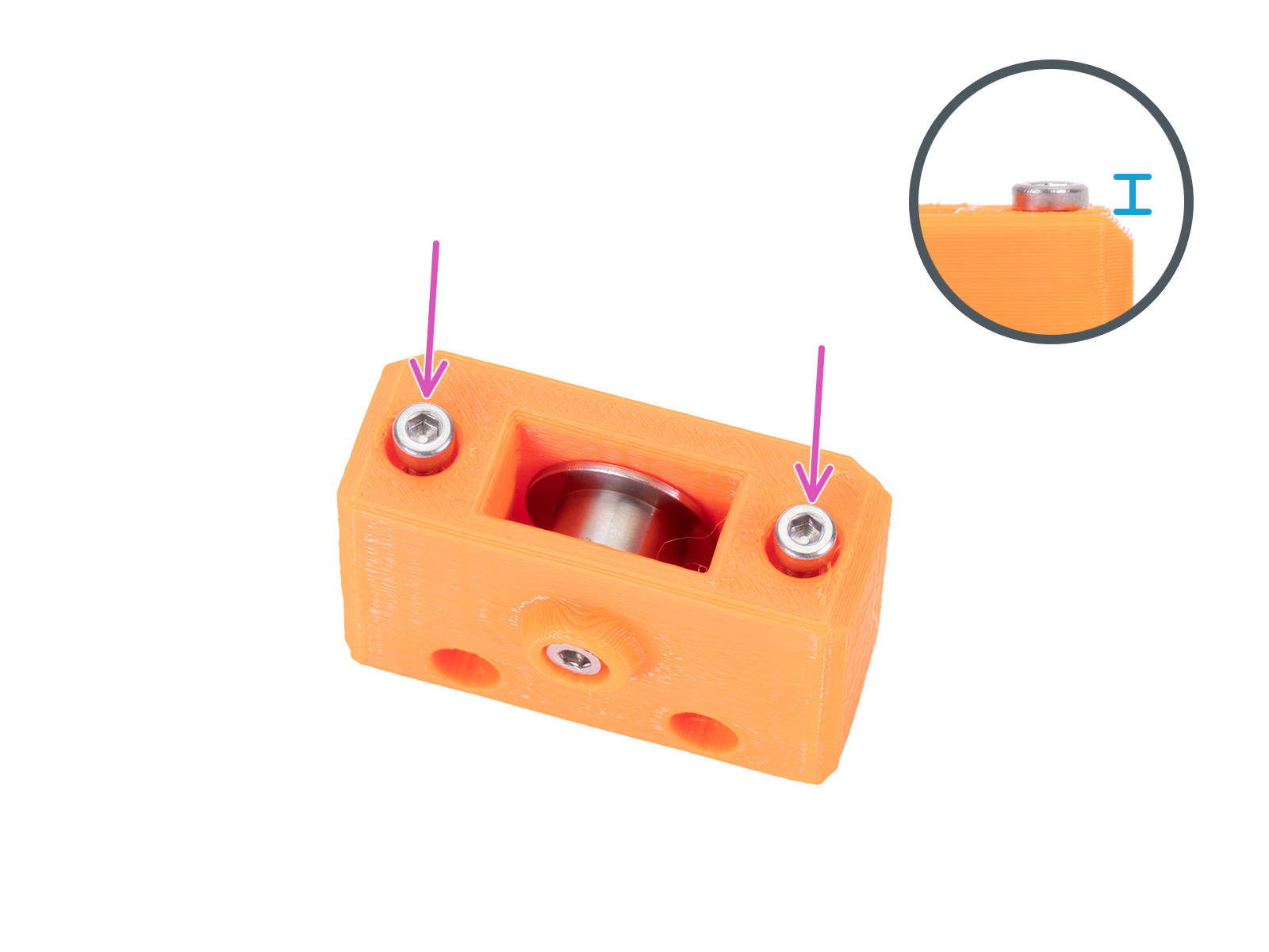
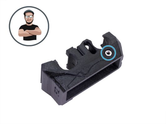
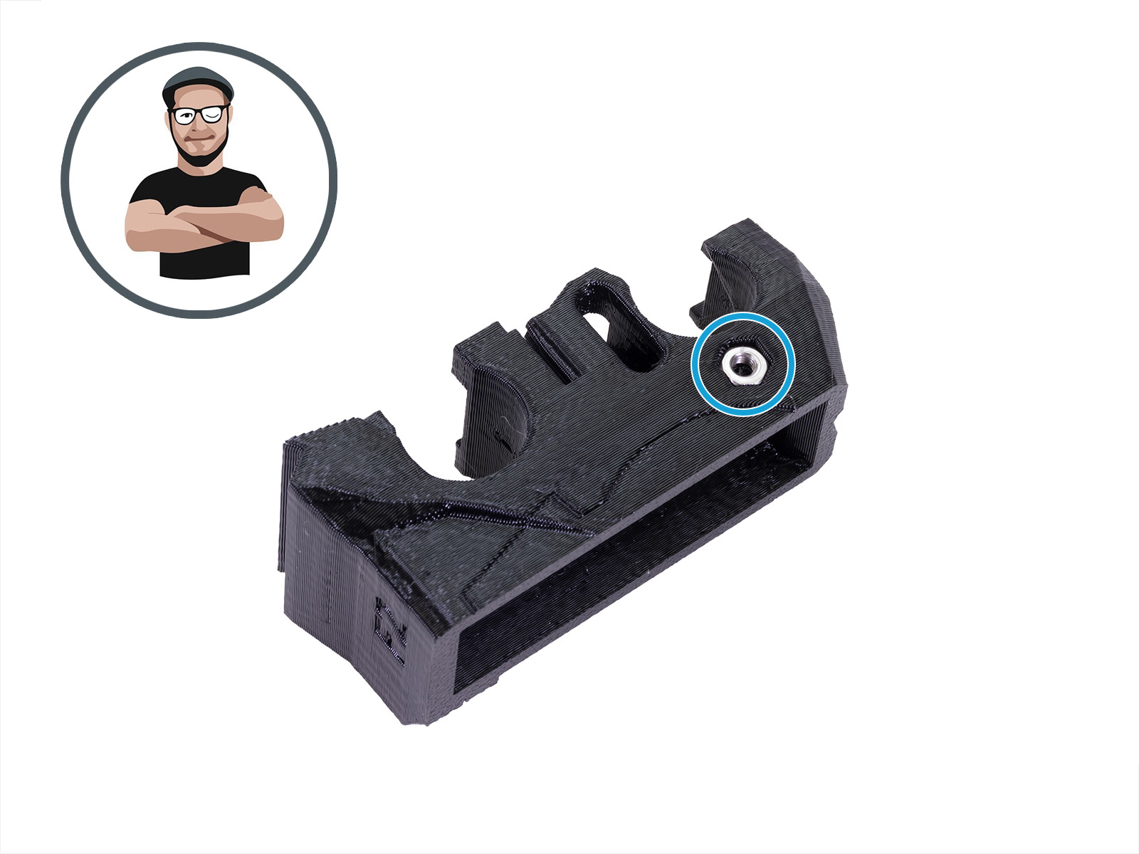
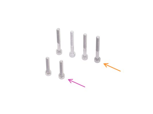
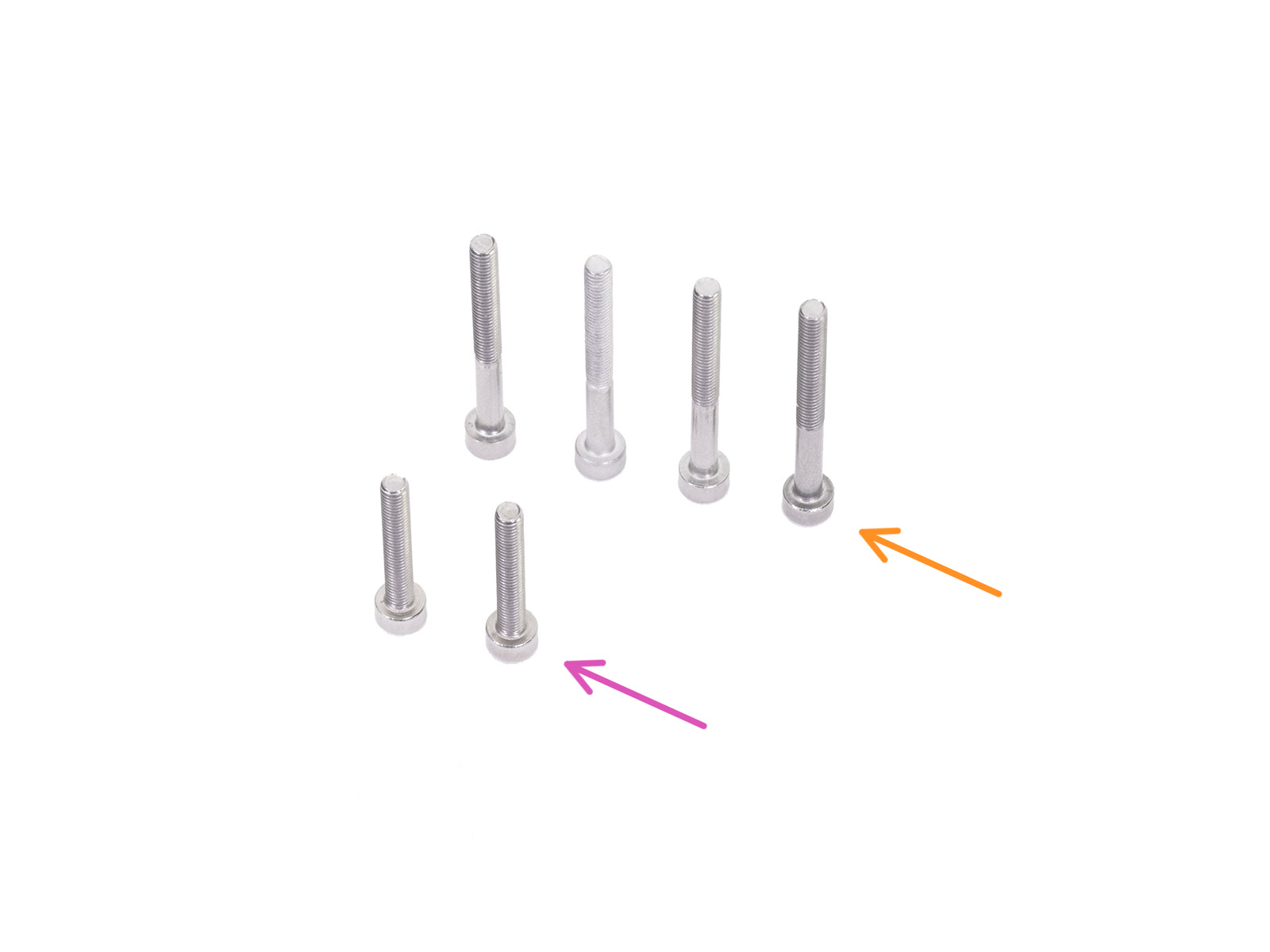
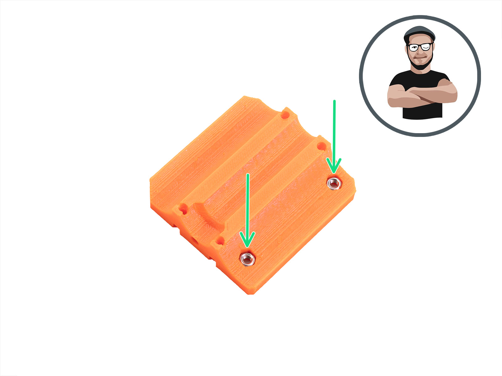
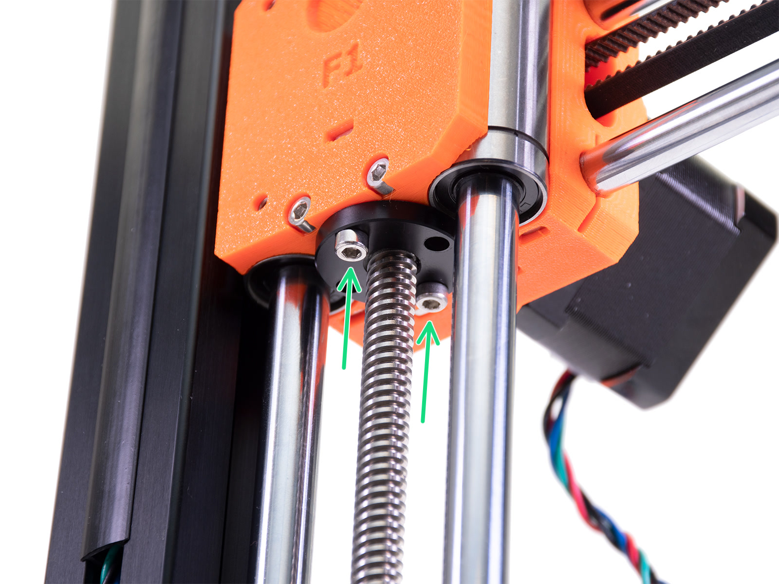
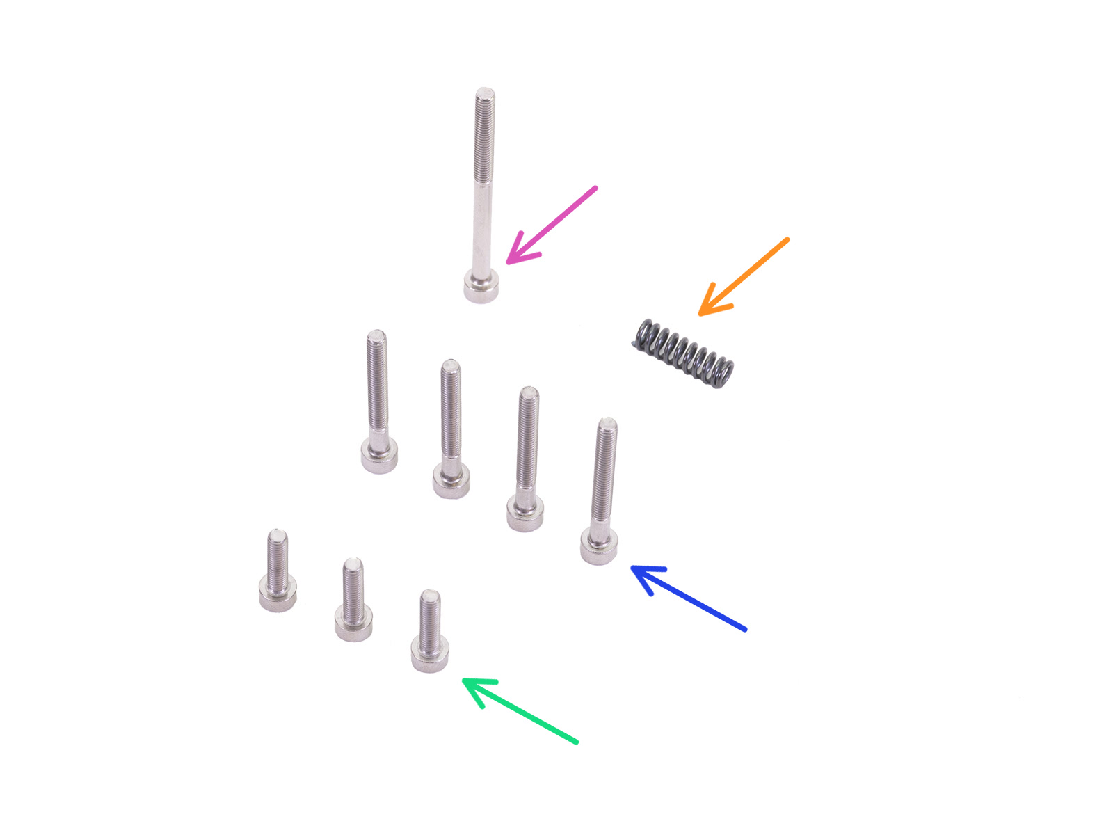
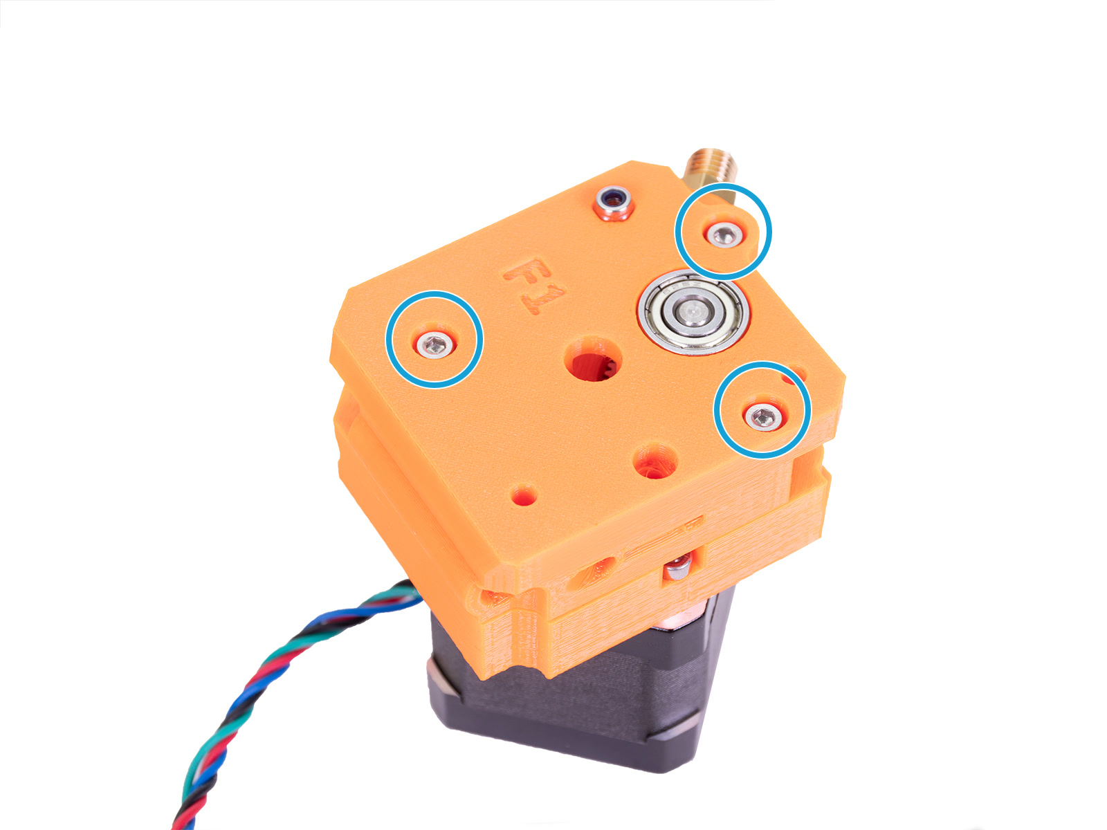
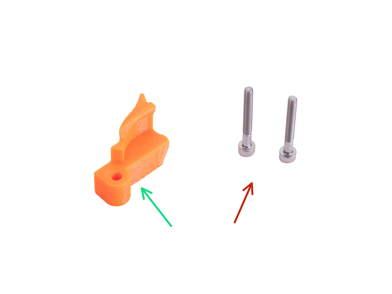
⬢Secure all parts together with four M3x12 screws.
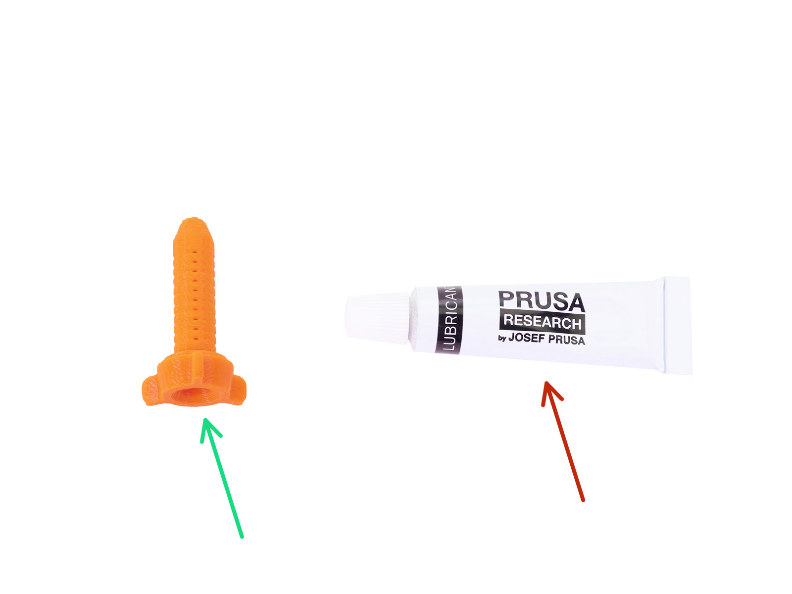
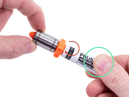
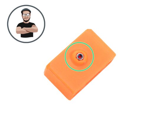
⬢Turn the tube and applicator counterclockwise until you feel a slight resistance. This means that the holes in the applicator are aligned with the ball rows.
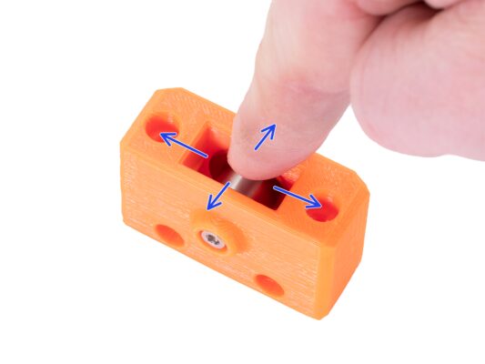
⬢Gently press the tube to push the lubricant into the ball rows of the bearing.
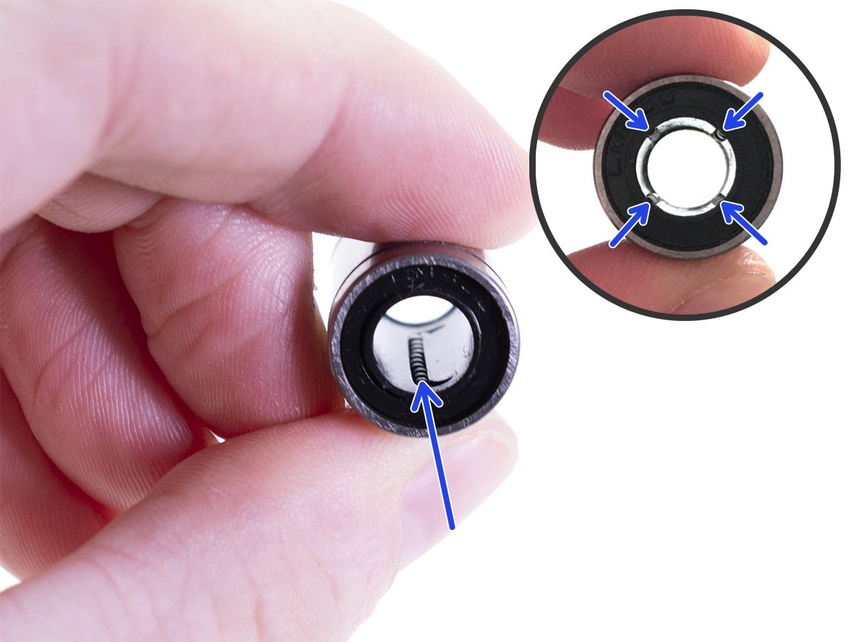
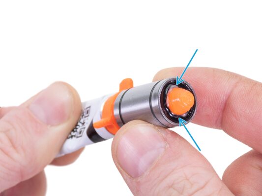
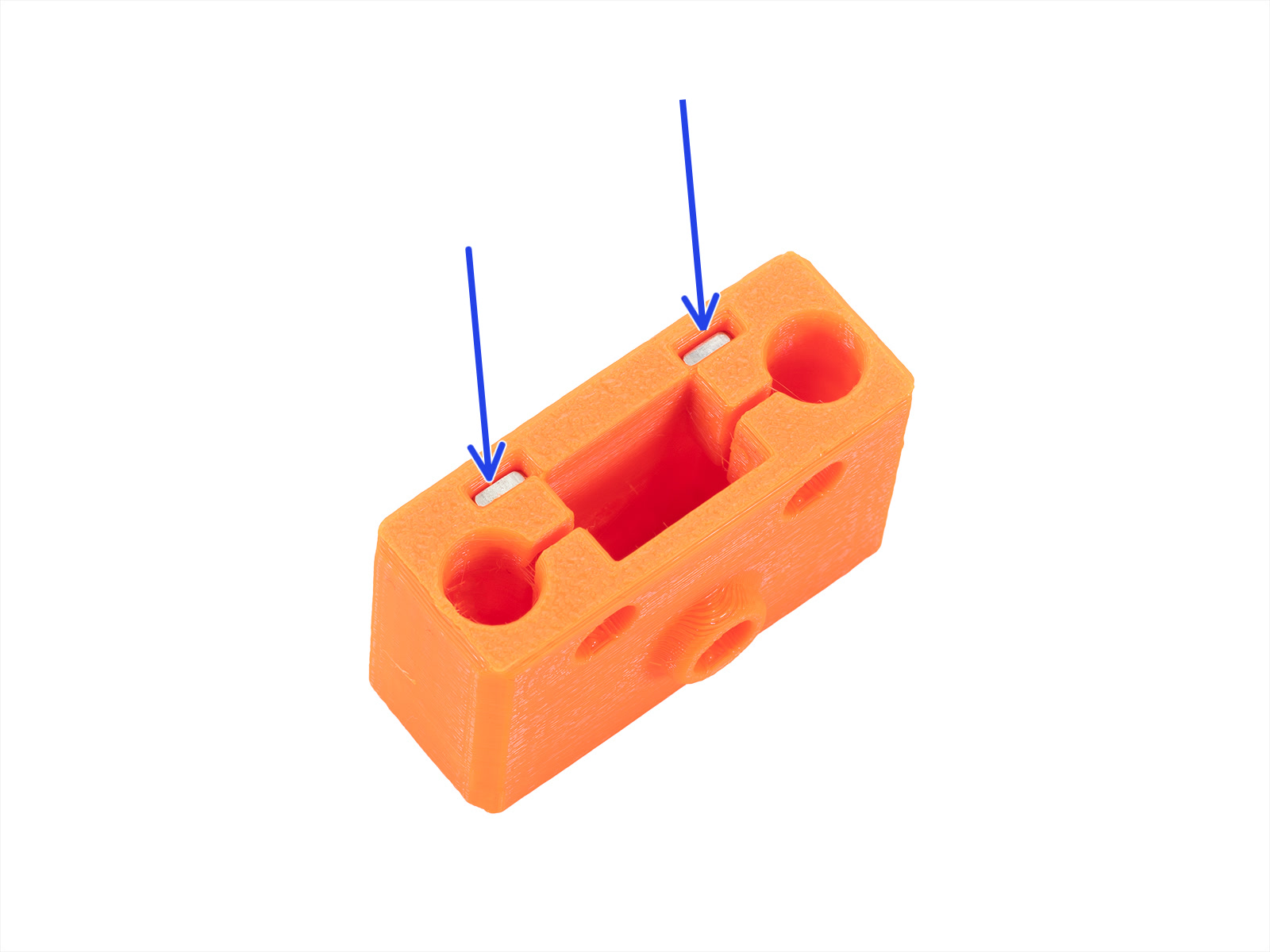
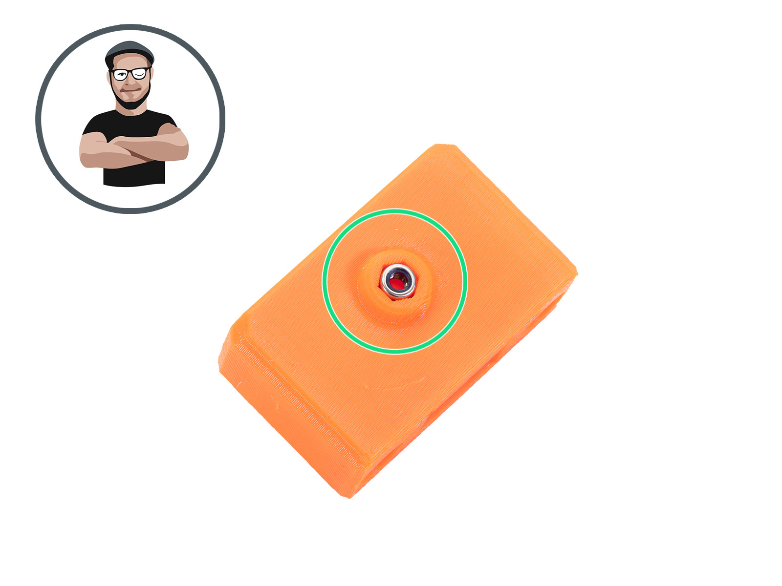
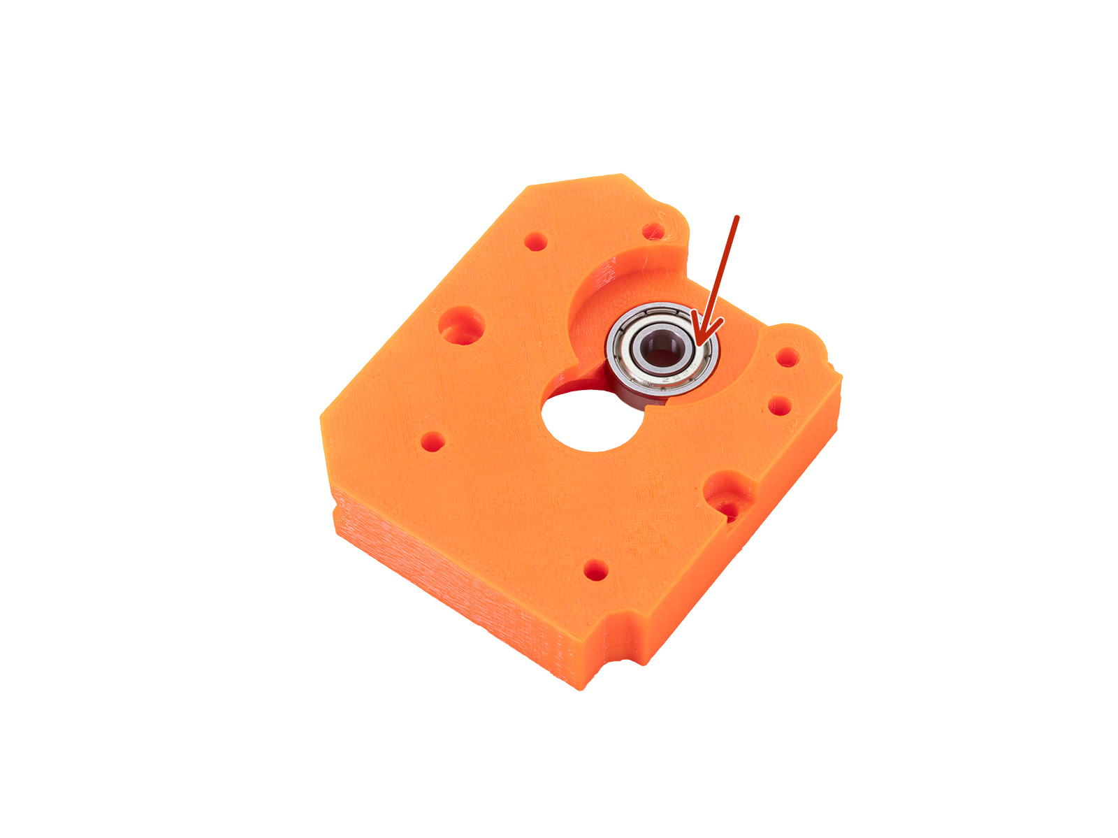
⬢Look at the front of the bearing. When the applicator pushes the lubricant out (around the black gasket), stop pressing the tube. Hold the bearing with the other hand during the lubricating.
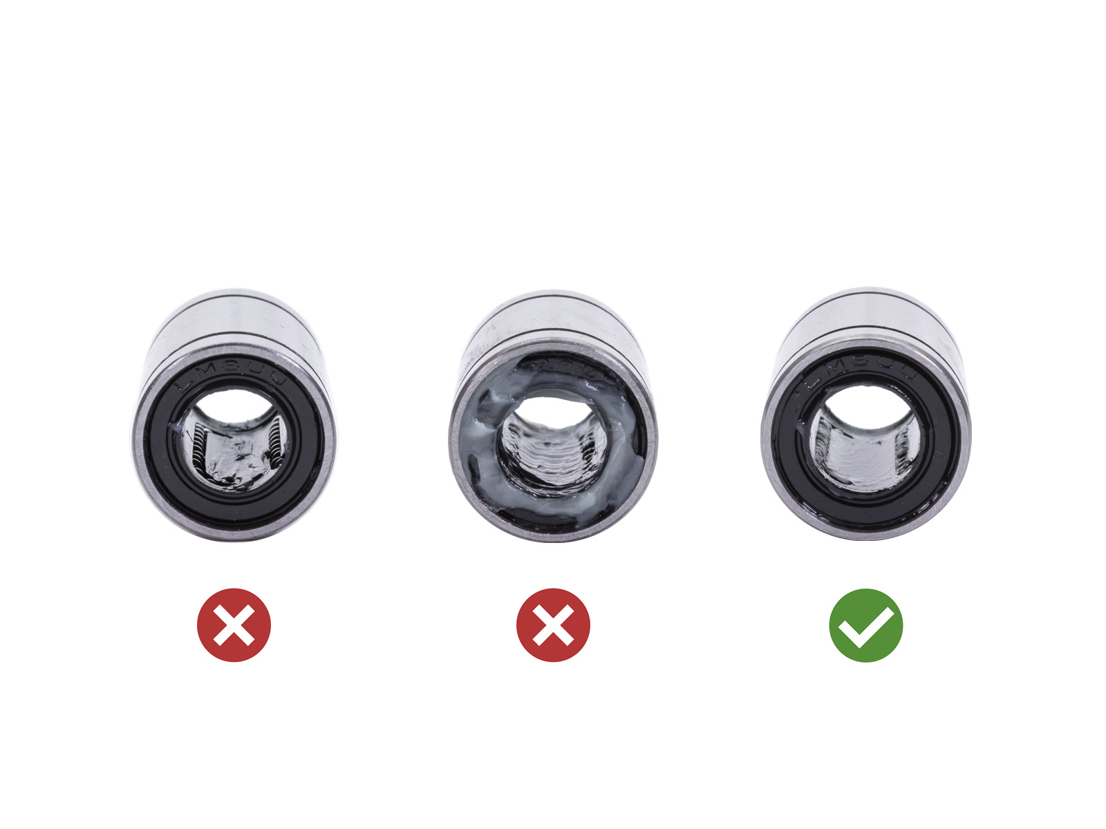
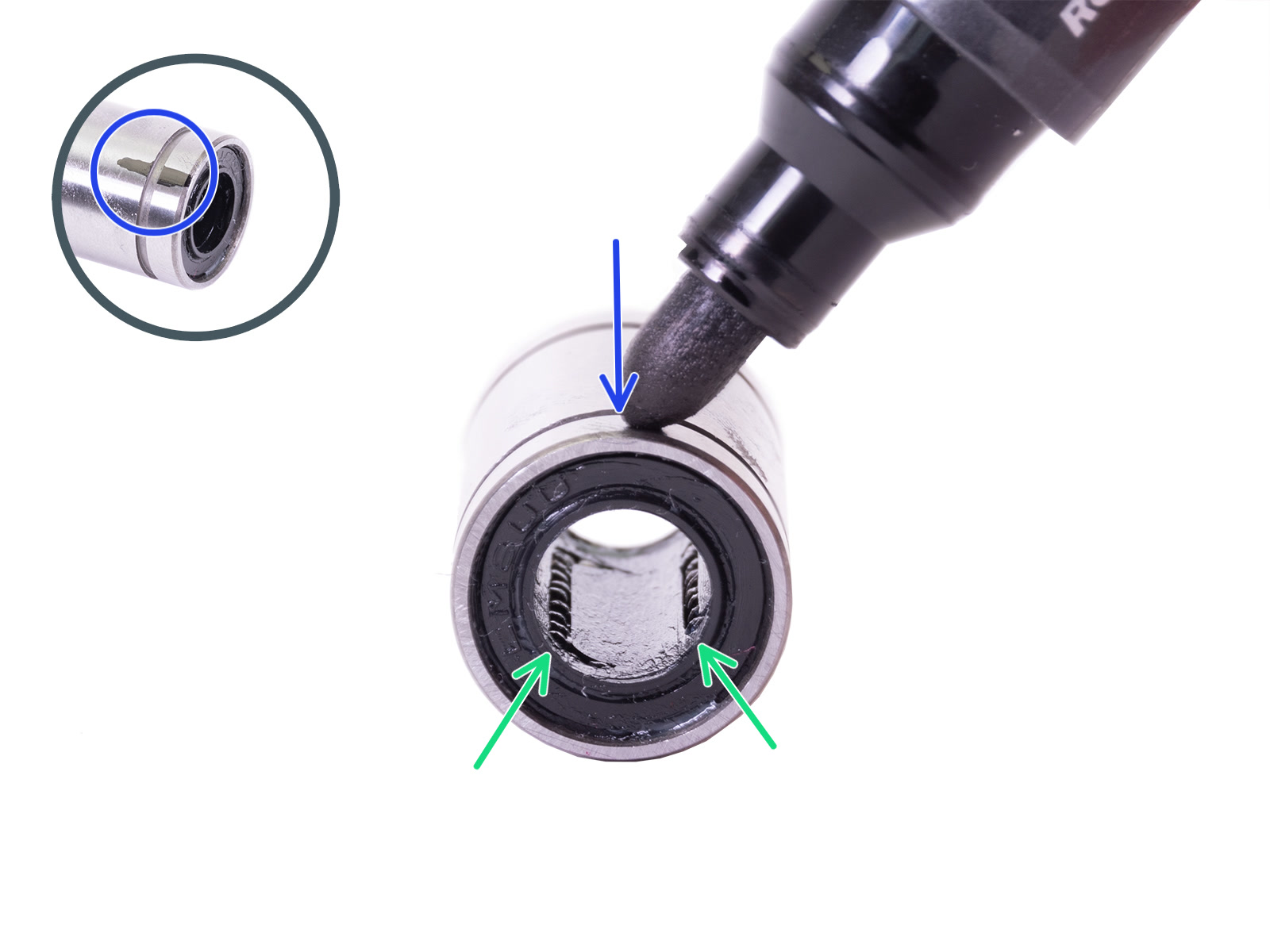
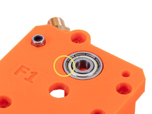
The grease must be spread evenly over all four ball rows inside the bearing. There must not be too much grease, or too little. Take a closer look at the last picture.
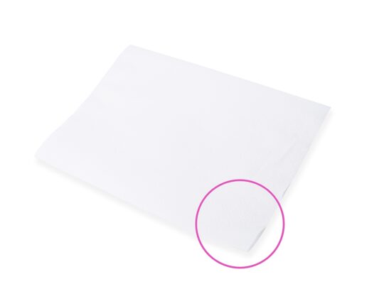
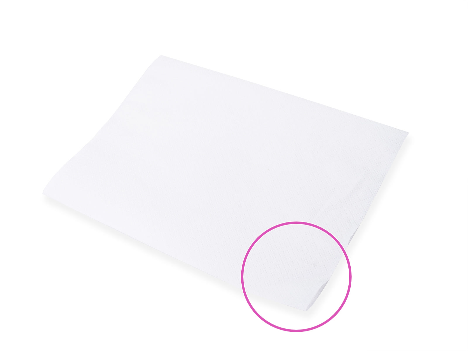
⬢Wipe off excess grease on the outside of the bearing with a paper towel.
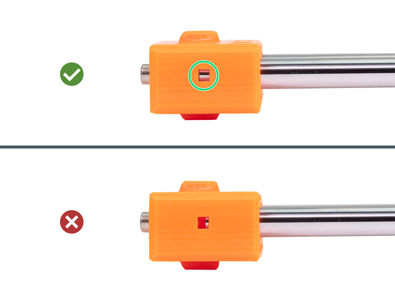
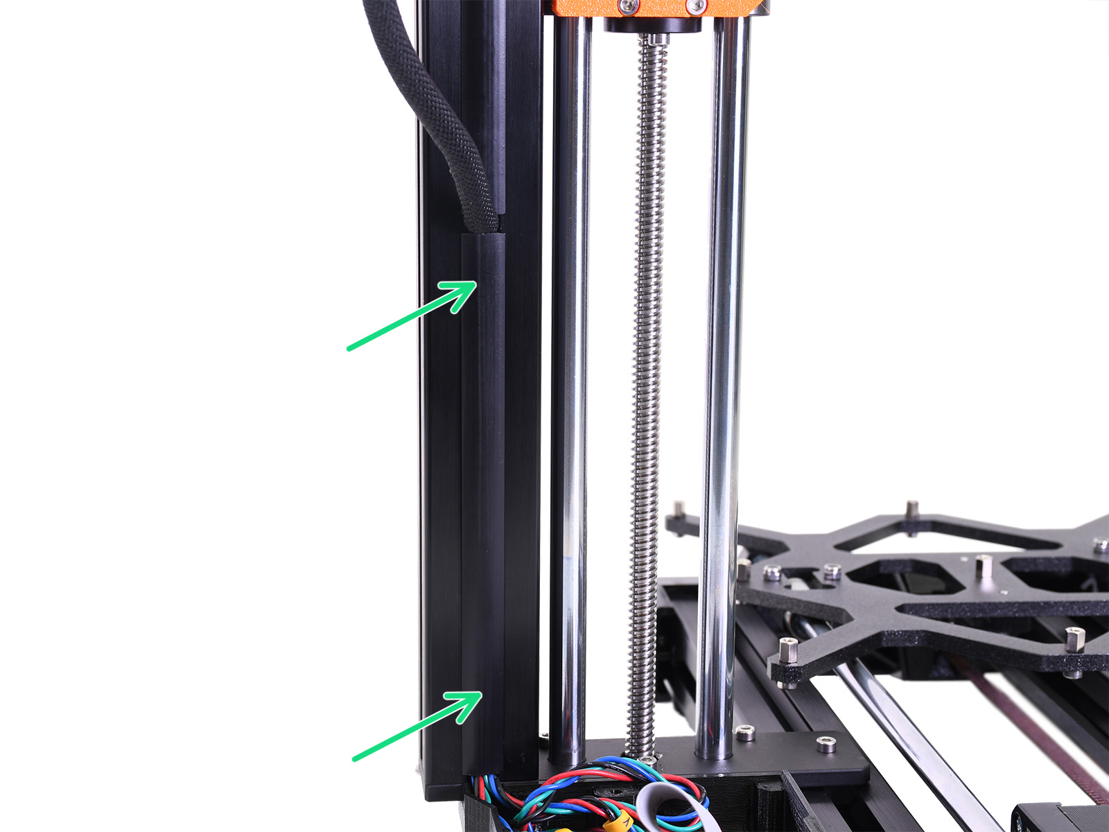
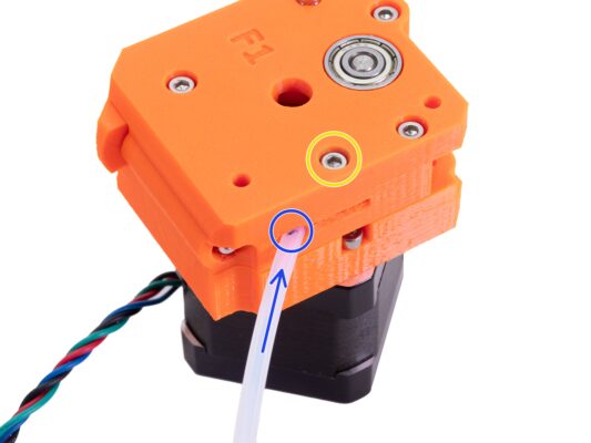
⬢Look sideways on the MINI-X-end into the inspection hole and ensure that the smooth rod is inserted all the way in the plastic part.
Some early units may be without inspection holes.
If the rod is not fully visible in the groove, try using more force to push MINI-X-end on the rod. Do not use a hammer or similar tools to push the plastic part!
⬢Turn the X-axis and use the same procedure for the second smooth rod.
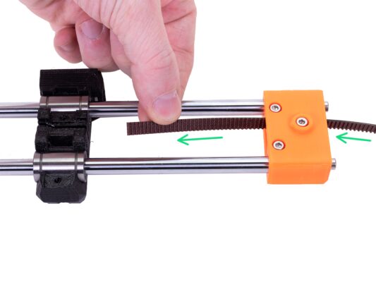
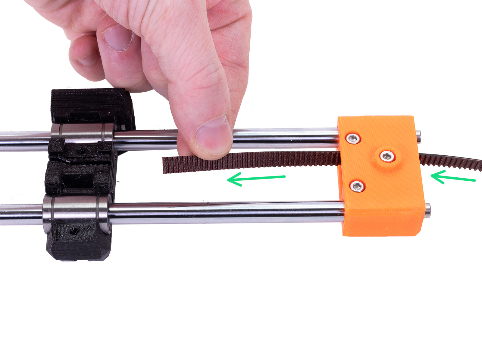
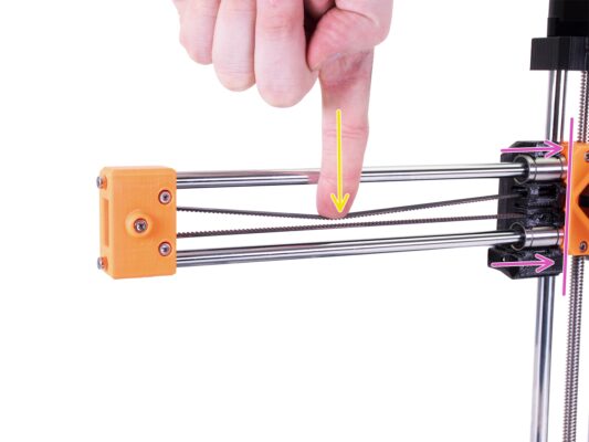
⬢Move the X-carriage all the way to the Z-carriage.
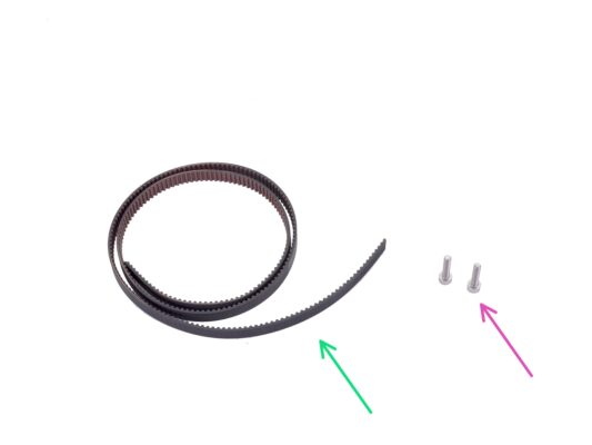
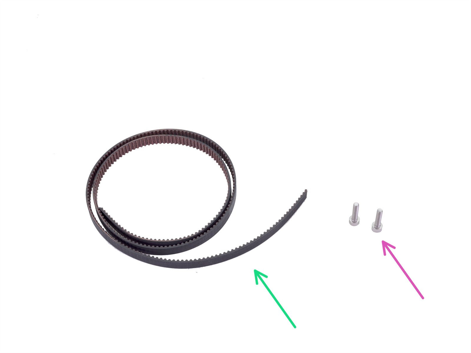
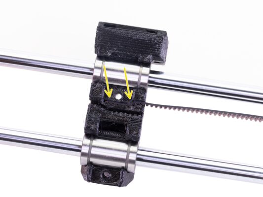
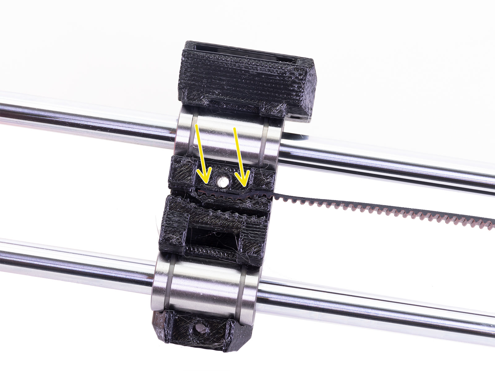
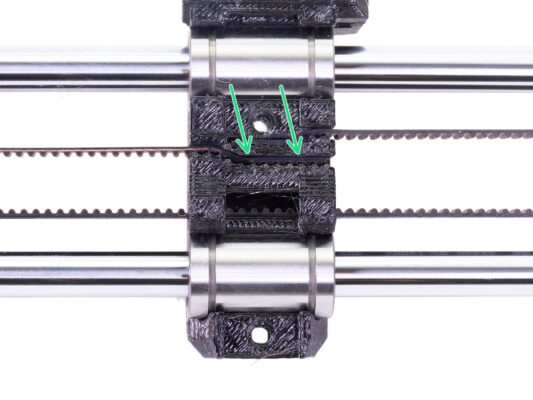
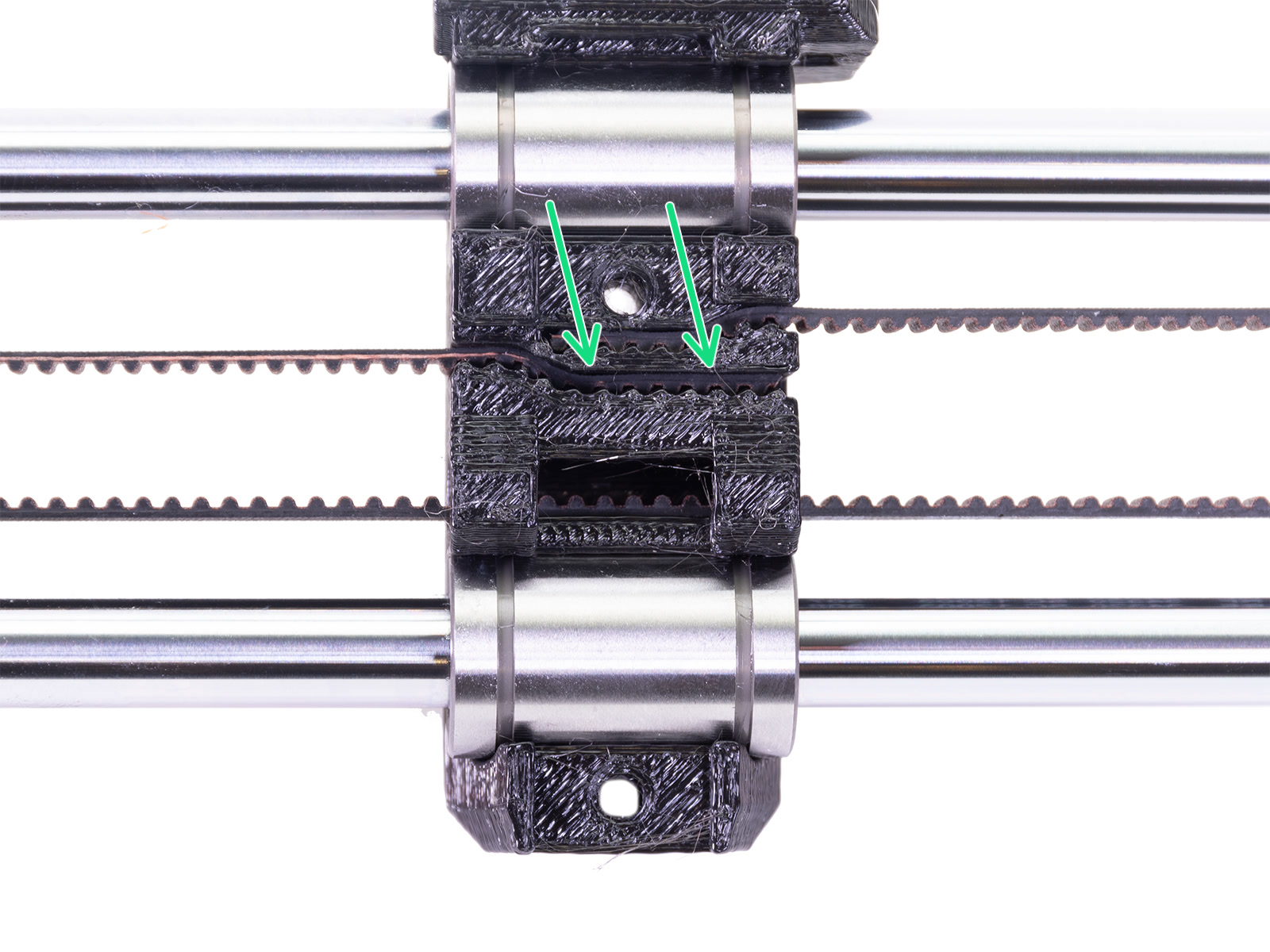
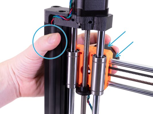
⬢Using a finger on your left hand push the belt down in the center of the X-axis. Some force should be needed for bending the belt, BUT don't try to overstretch the belt as you might damage the printer.
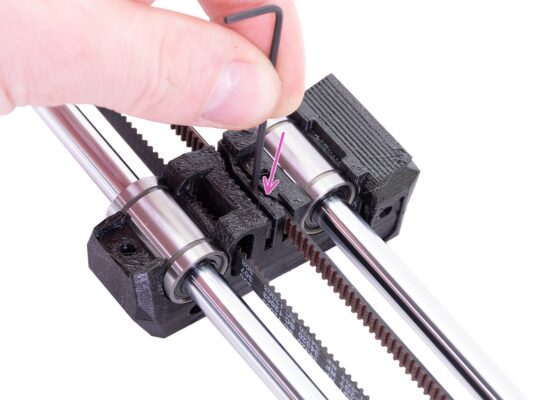
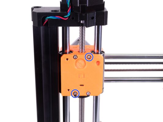
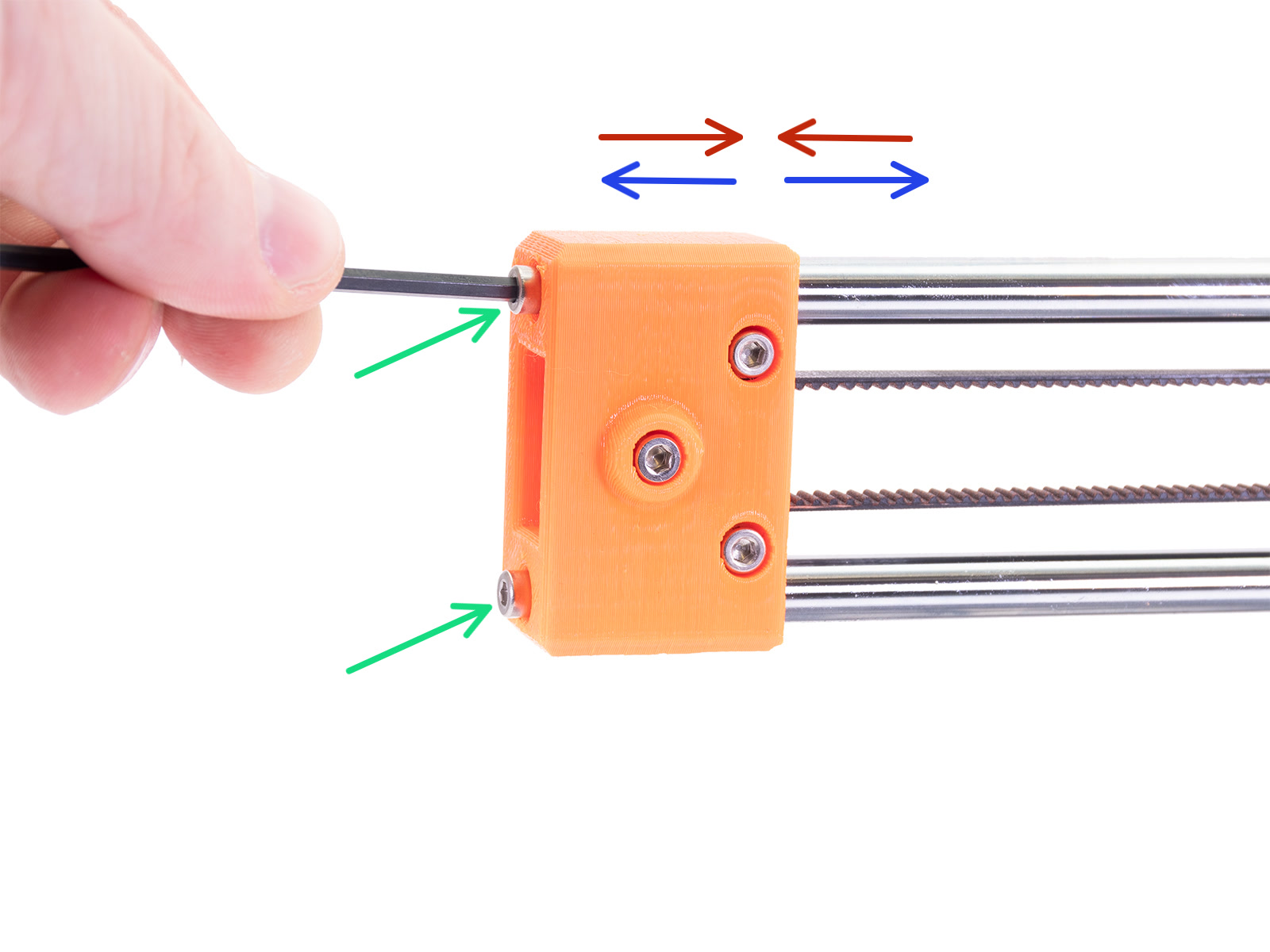
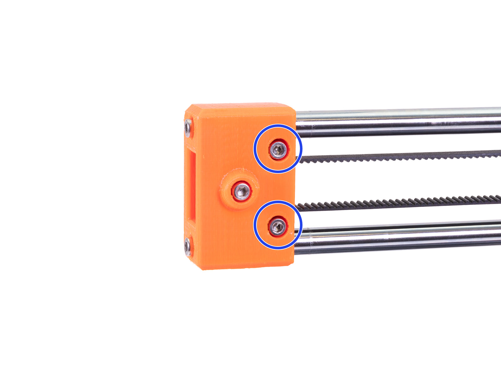
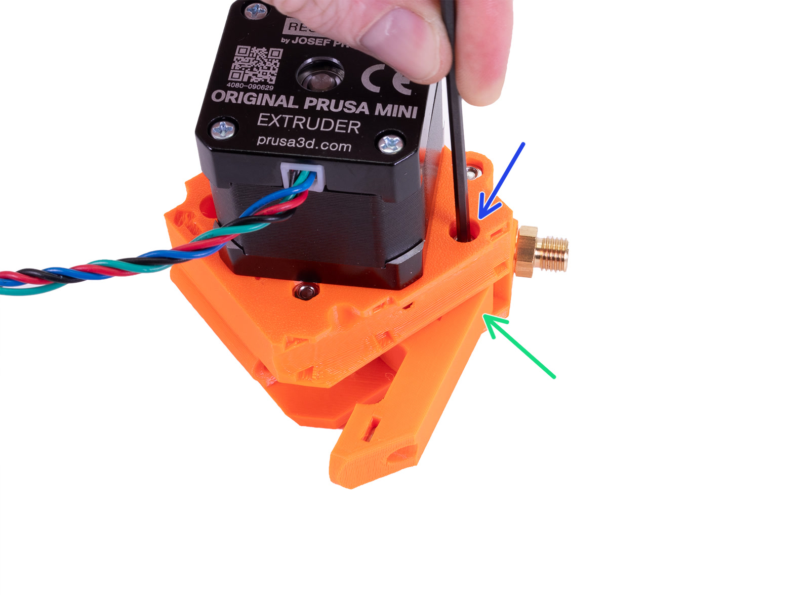
⬢Adjust it by releasing or tightening both screws on the X-end.
⬢Release the screws, bring the X-end closer to rods and thus decrease the overall tension.
⬢Tighten the screws, X-end will move apart, the overall tension will increase.
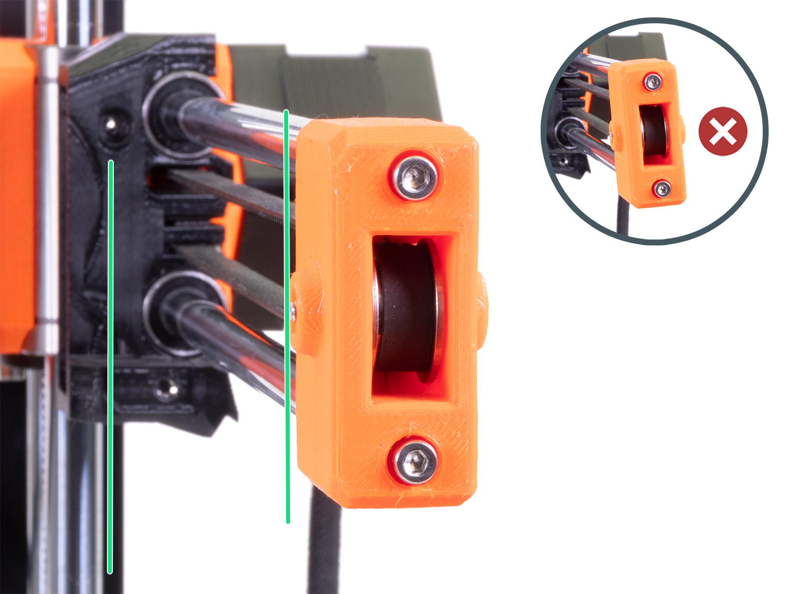
⬢Look at the X-axis from the side. Align the X-end parallel to the Z-axis smooth rods by twisting the plastic part. Do not use too much force to twist, you may damage the X-axis.
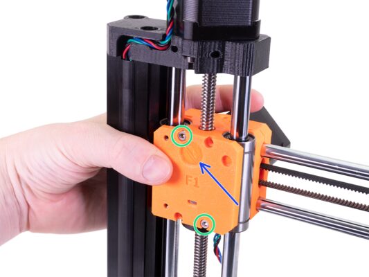
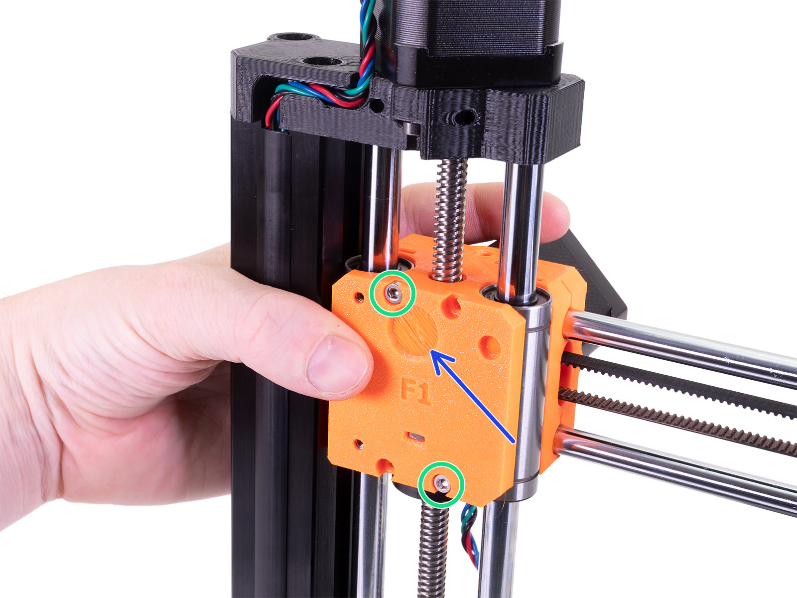
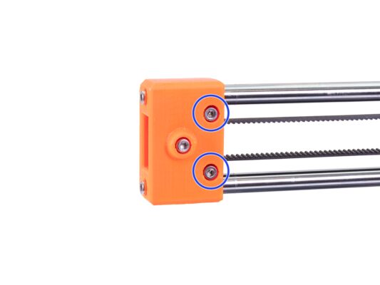
⬢Securing the X-end by tightening both screws on the front side of the plastic part.
After tightening, check once more the X-end is parallel with the Z-axis.
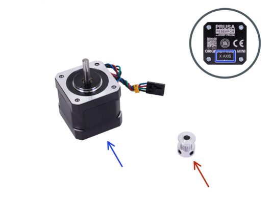
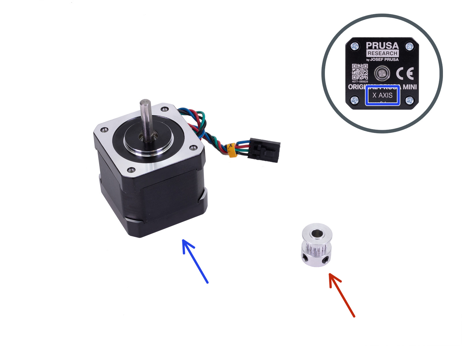
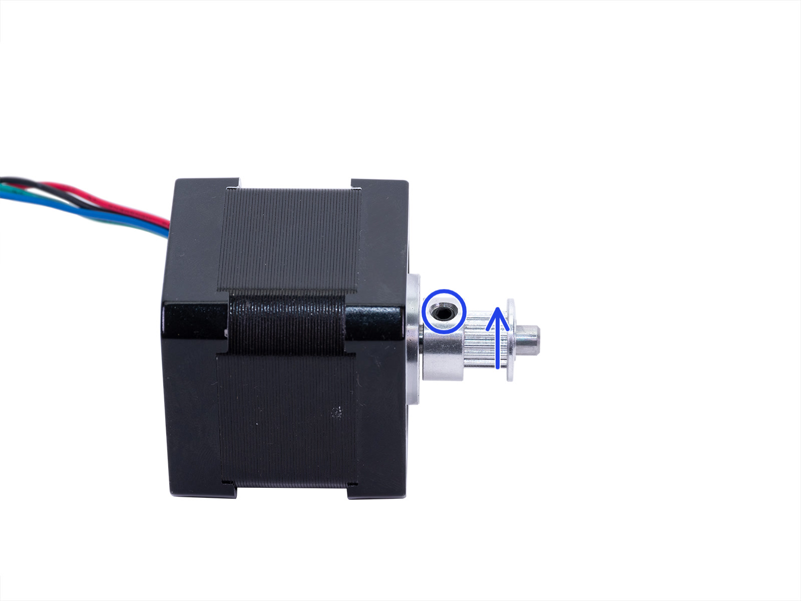
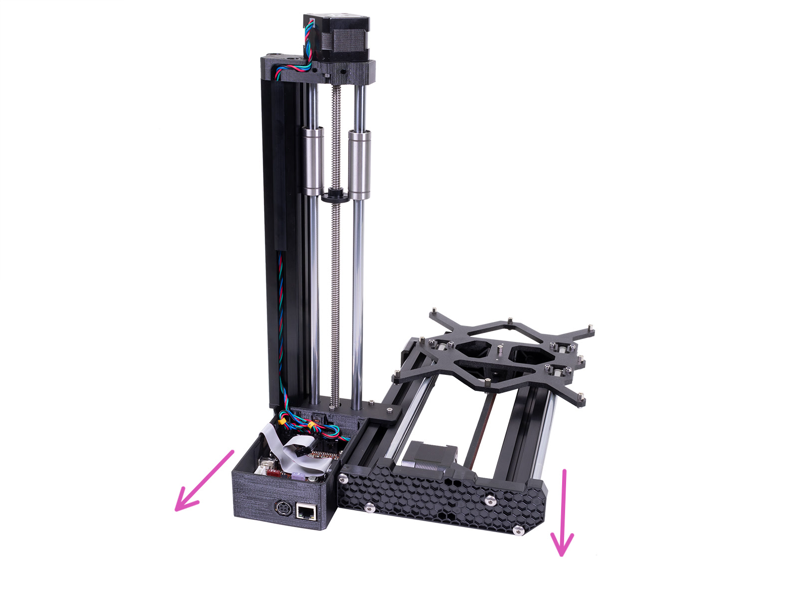
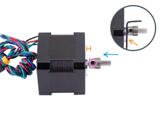
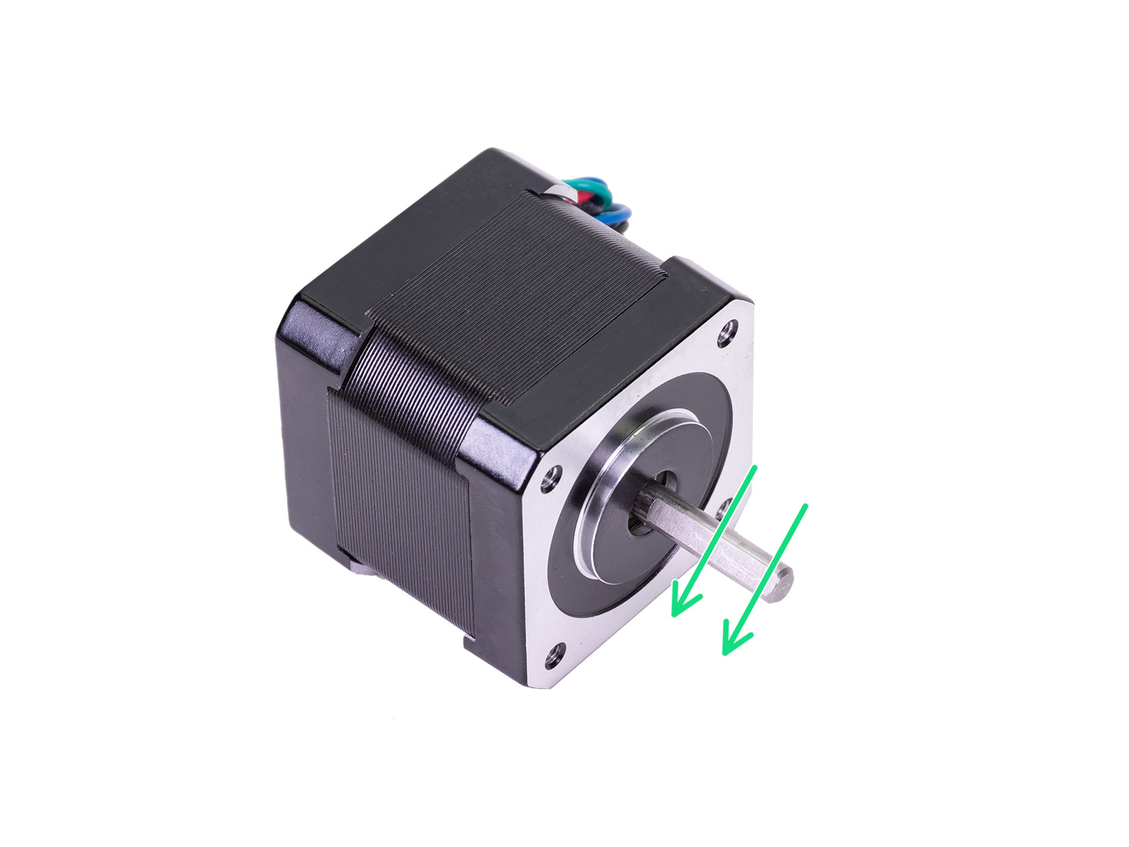
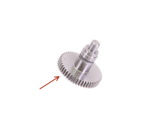
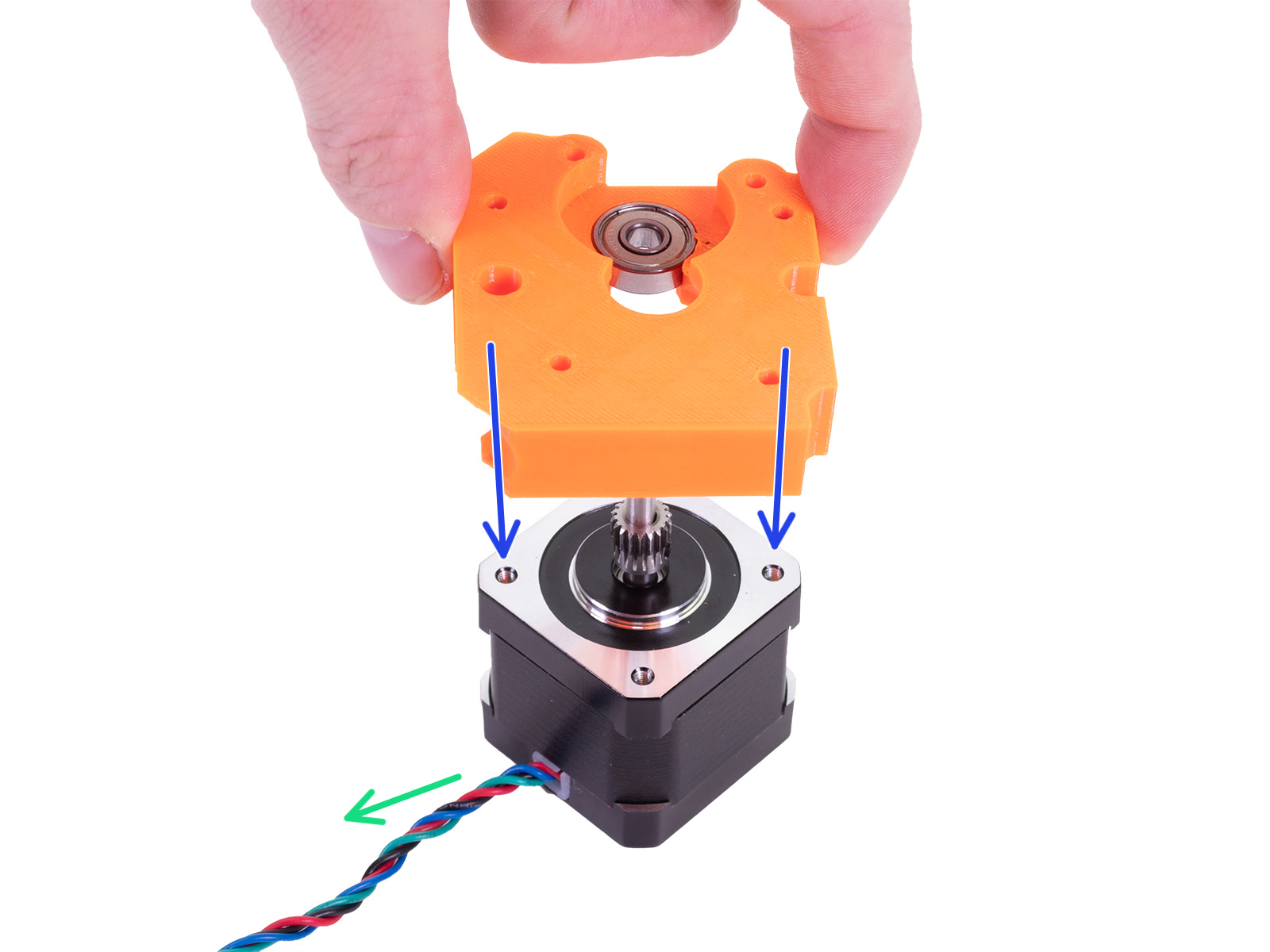
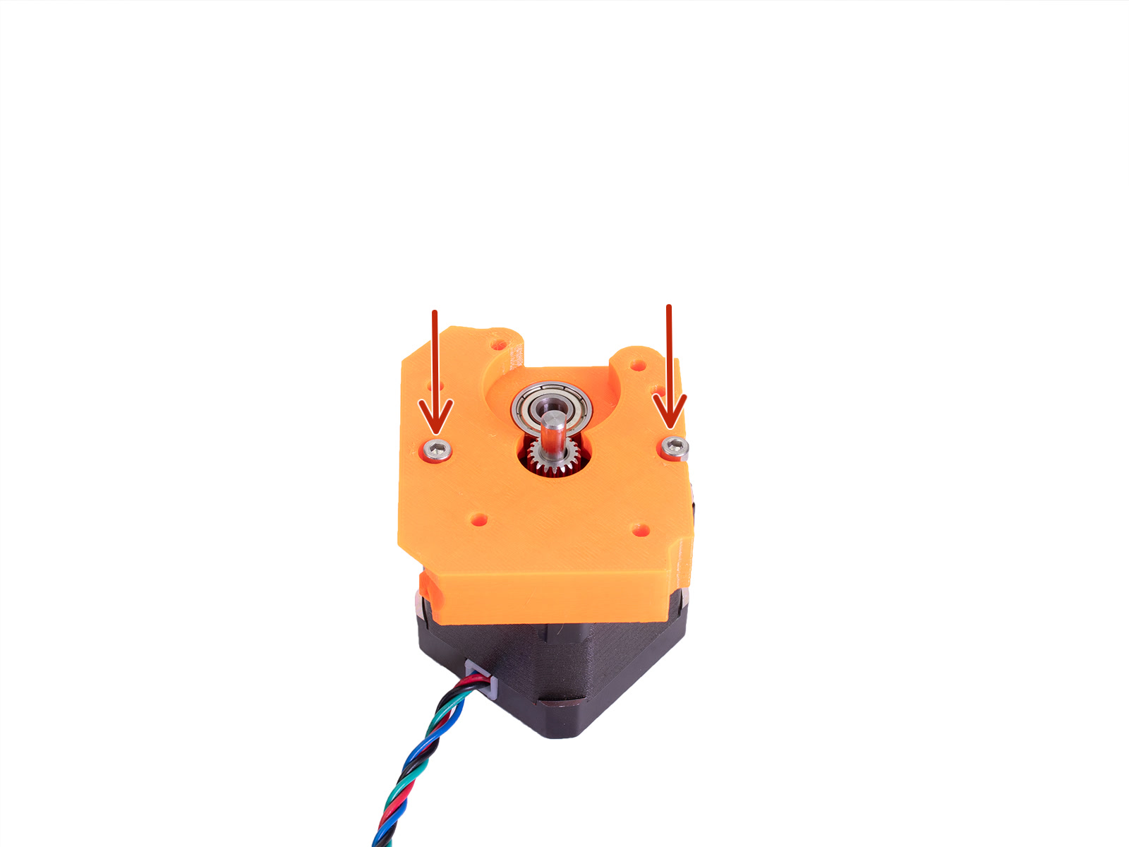
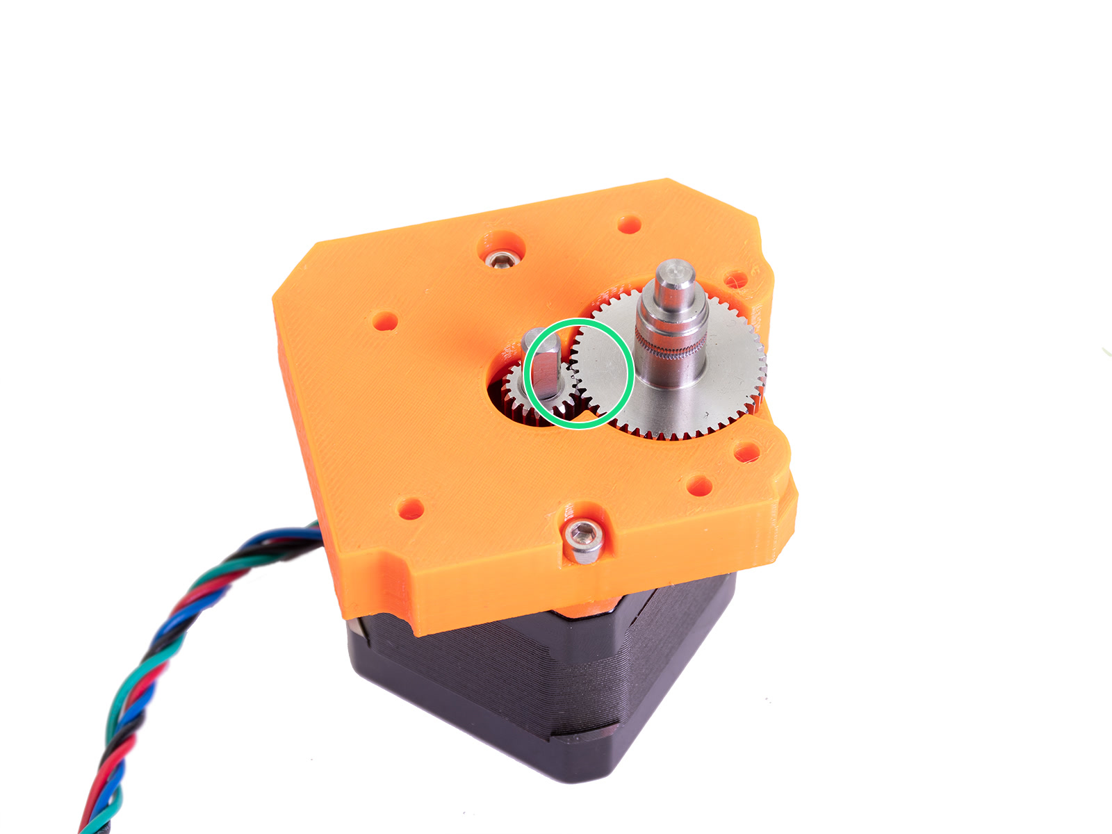
⬢There is a flat part on the motor shaft. Rotate it similarly to the first picture. See the direction of the arrows.
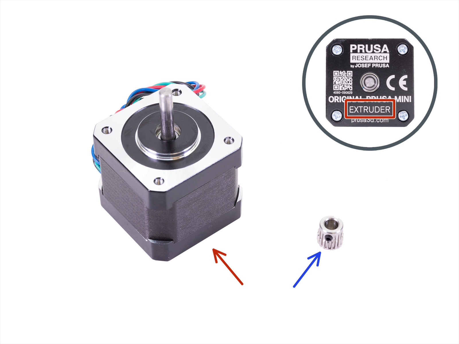
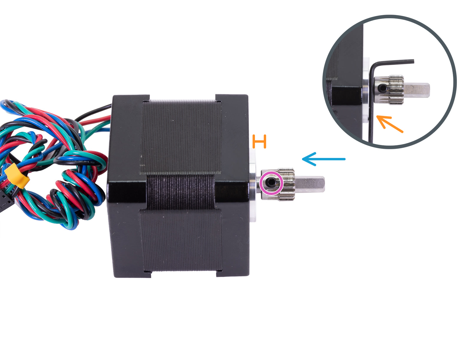
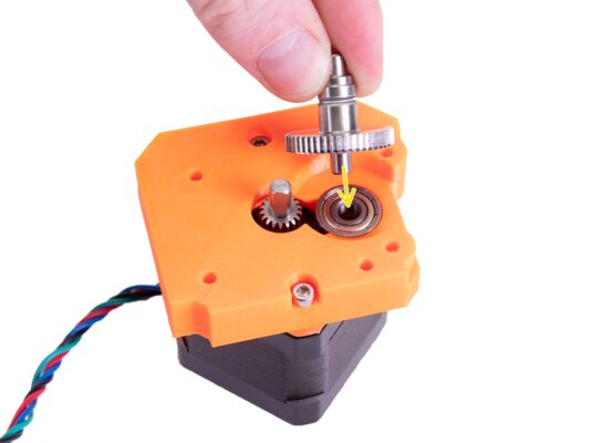
⬢Place the Extruder pinion on the Extruder motor shaft as shown in the picture.
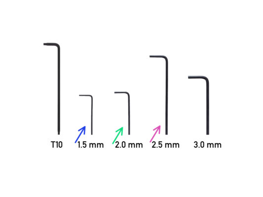
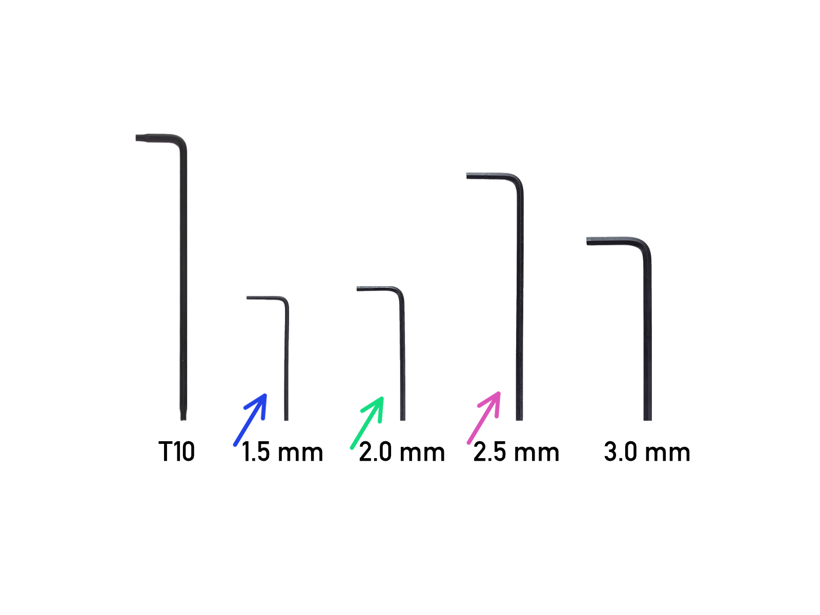
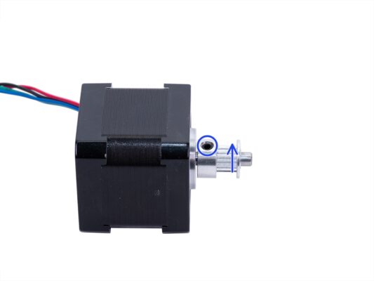
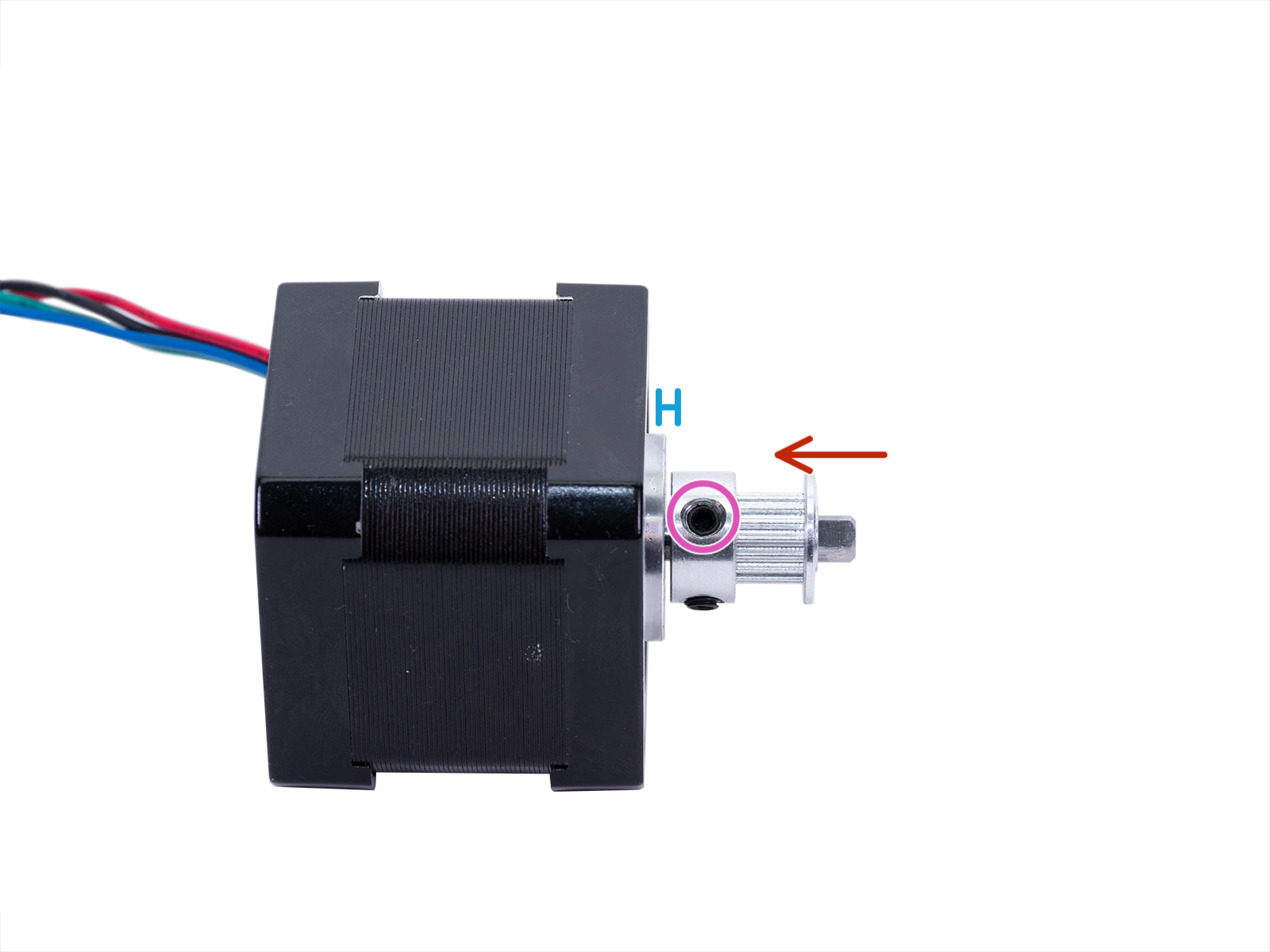
⬢Don't press the pinion against the motor. Leave a 1.5 millimeters gap between both parts. You can use the 1.5mm Allen key to set the gap.
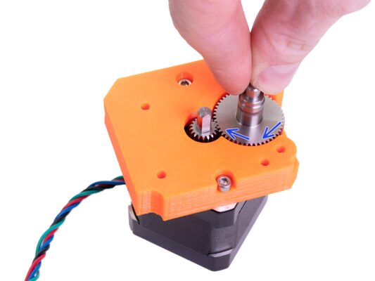
⬢The set screw must be facing directly against the pad (flat part) on the shaft. Tighten the screw with the longest part of the Allen key. Be careful, not to strip the screw.
Ensure you have the correct orientation of the pulley on the shaft. It can be placed both ways, but only one is correct.
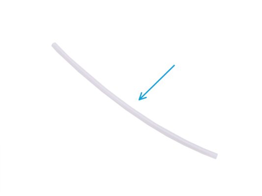
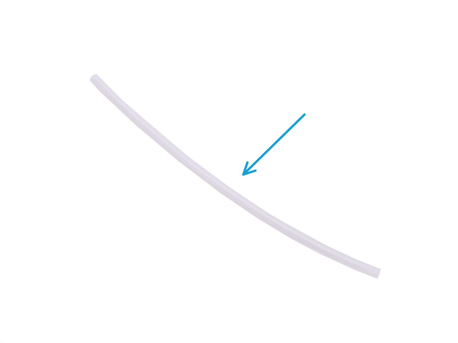
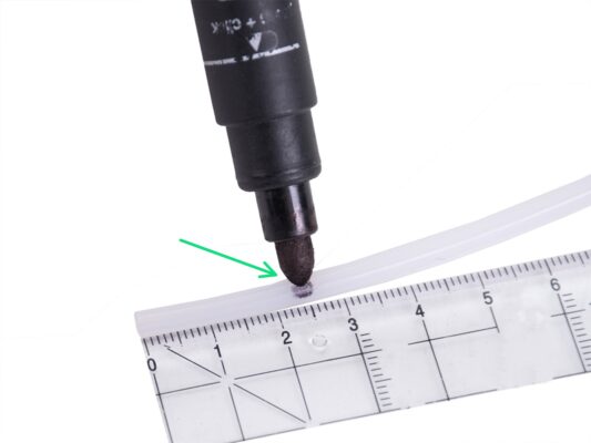
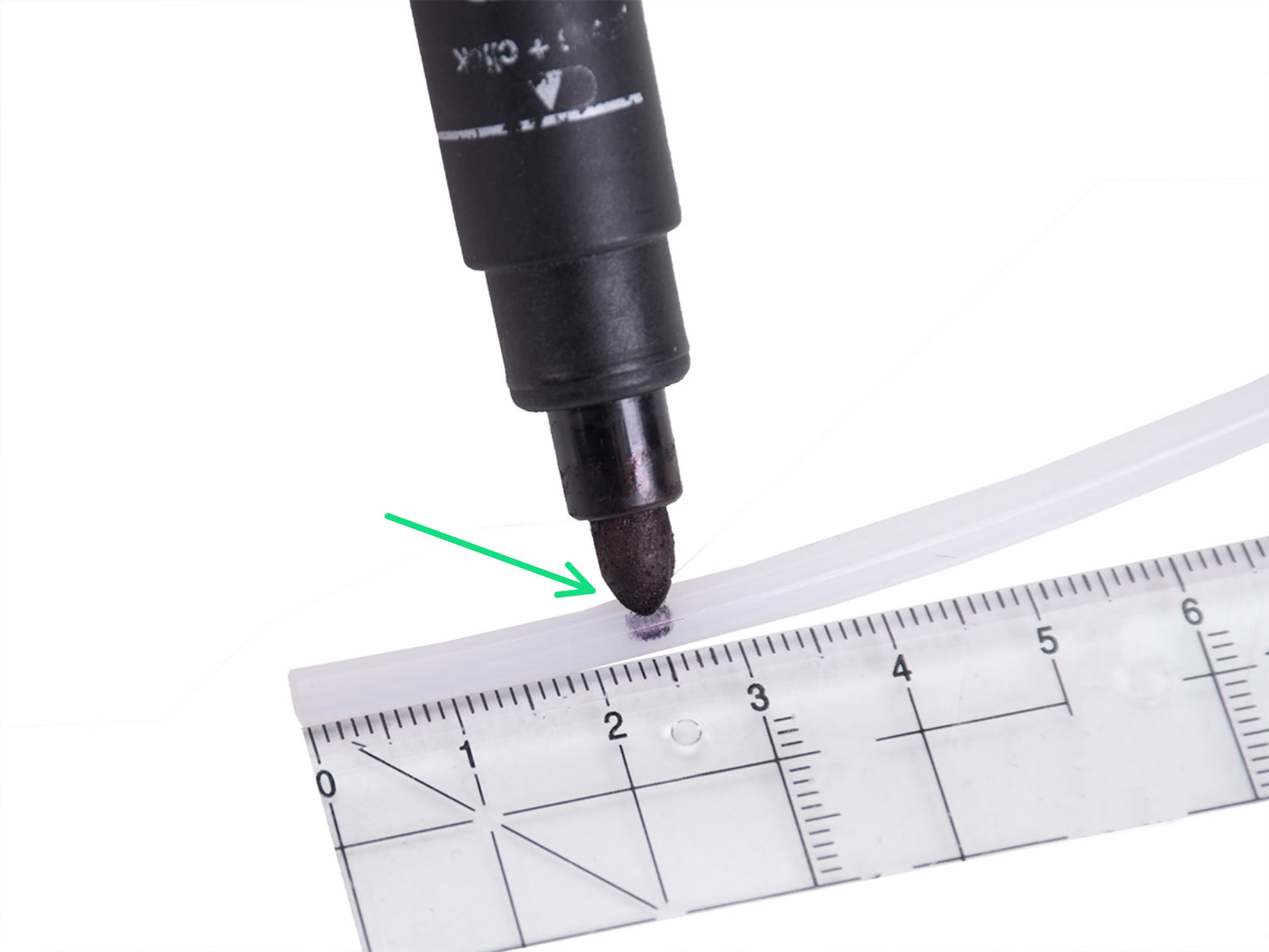
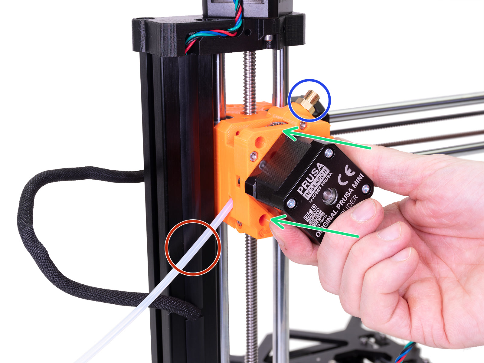
⬢It's recommended to mark the distance of 2.5 cm (0.98 inches) from the end of the PTFE tube before the insertion to the extruder. Both ends are symmetrical.
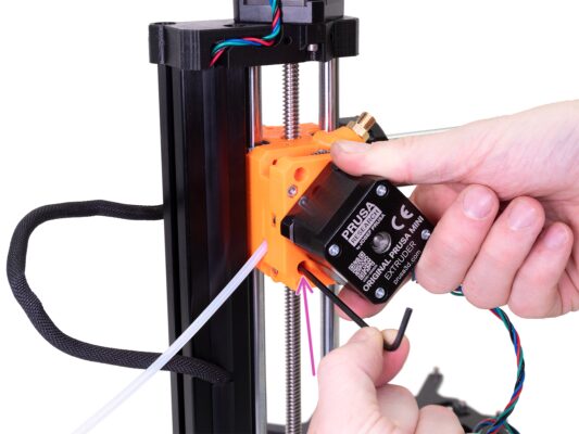
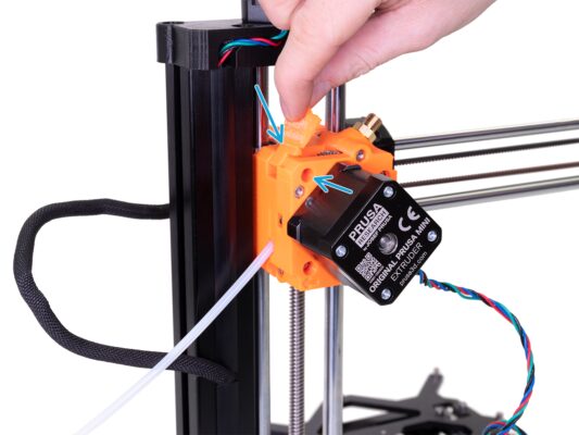
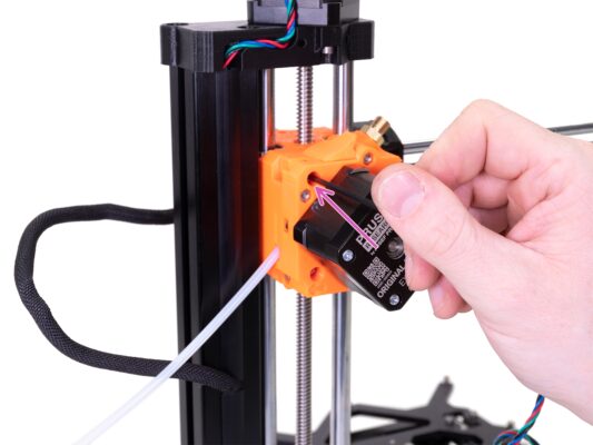
⬢Locate the hole for the PTFE tube on the side of the extruder assembly and insert the marked end of the tube all the way to the extruder. Check the correct insertion according to the marking on the tube.
⬢Now it's time to the next chapter: 4.Printhead & Heatbed assembly
Was this guide helpful?
Comments
Still have questions?
If you have a question about something that isn't covered here, check out our additional resources. And if that doesn't do the trick, you can send an inquiry to [email protected] or through the button below.