English

1. Tools necessary for this chapter
Step 1 of 58 (Chapter 3 of 5)
Contents
Comments
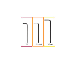
⬢For this chapter, please prepare:
⬢T10 Torx key
You can also use a T10 screwdriver, which is included in the package
⬢2.5 mm Allen key
⬢4.0 mm Allen key
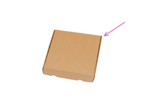
⬢A cardboard box is to be used as heatbed protection during the setup. Hint: you can use the Nextruder box shipped with your printer.
Loading...
Contents
Original Prusa XL Five-Head (Assembled) (1.07)
- 1. Introduction
- 2. Printer unboxing
- 3. Printer set up
- Tools necessary for this chapter
- Injection molded xLCD: parts preparation
- Injection molded xLCD: xLCD cables
- Injection molded xLCD: mounting the xLCD
- xLCD: parts preparation
- Mounting the xLCD
- Mounting the xLCD
- Preparing the printer
- Nextruder cable: parts preparation
- Nozzle seal versions
- Version C: preparing the dock
- Guiding the nextruder cable
- Attaching the first and second nextruder dock
- Dock inspection
- Dock inspection: video
- Third dock: screw removing
- Version C: Nozzle seal: parts preparation
- Version C: Assembling the Nozzle seal
- Version C: Installing the nextruder nozzle seal
- Wi-Fi antenna holder versions
- Version A: Connecting the nextruder cables
- Version A: Removing the XL buddy box cover
- Version A: Connecting the Nextruder cables
- Version A: Covering the XL buddy box
- Version A: Guiding the PTFE tubes
- Version A: Guiding the docks PTFE tubes
- Version A: Installing the Wi-Fi antenna: parts preparation
- Version A: Installing the Wi-Fi antenna
- Version B: Wi-Fi antenna holder: parts preparation
- Version B: Installing the Wi-Fi antenna: antenna preparing
- Version B: Installing the Wi-Fi antenna: antenna preparing
- Version B: Connecting the nextruder cables
- Version B: Installing the Wi-Fi antenna holder
- Version B: Connecting the Nextruder cables
- Version B: XL buddy box covering
- Version B: Guiding the docks PTFE tubes
- Version B: Guiding the PTFE tubes
- Version B: Installing the Wi-Fi antenna: parts preparation
- Version B: Installing the Wi-Fi antenna
- Spool holder assembly versions
- Version A: Spool holder: parts preparation
- Version A: Spool holder: left side
- Version A: Assembling the spool holder
- Version A: Mounting the spool holder assembly
- Version A: Spool holder: right side assembly
- Version B: Assembling the spool holder: parts preparation
- Version B: Assembling the spool holder: adjusting the nut
- Version B: Assembling the spool holder
- Version B: Preparing the spool holder
- Version B: Spool holder: left side assembly
- Version B: Spool holder: right side assembly
- Nextruder assembly: parts preparation
- Docking the Nextruder
- Nextruder cable bundle assembly
- Nextruder cable bundle assembly versions
- Version A: Nextruder cable bundle assembly
- Version B: Nextruder cable bundle assembly
- Almost done!
- 5. First run
- Manual changelog Five-Head (Assembled)
Comments
Log in to post a comment
DavidHunter
•
A time estimate would be useful at the start of each chapter.
Reply